
Specifications
22
cause the alarm to trigger on setting, or give a warning via the siren that the door is
open when in actual fact it is not.
Do not connect
the boot to the door wire as, depending on which model of alarm,
this will give the wrong diagnostic code on the alarm LED if the boot is opened
when the alarm is set.
* Boot wire
-
Most modern cars have a boot light which will work on the same
principle
as the door wire. Test the same as for the door wire. Some cars,
particularly hatch back models, are already factory connected to the door circuit.
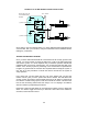
If the alarm has a dedicated boot wire then it can be connected directly to the boot
light control wire. I
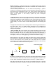
f not, then the boot light control wire should be connected to the
bonnet wire using a diode to isolate the two circuits and stop the opening of the
bonnet turning on the boot light. The diode will also prevent the battery from
flattening itself if the bon
net switch becomes faulty.
Once again, do not connect the boot light control wire to the doors.
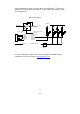
* Central locking wires
-
This is an area which a lot of installers find most
frustrating. The trick is to identify which sort of system is employed in the veh
icle.
Basically there are only a handful of different factory door lock circuits which fall
into distinct categories, such as Negative Pulse, Positive Pulse, and Reverse
Polarity. A few systems use Vacuum and/or Vacuum/electric designs. More recently
ther
e are some vehicles which use a single wire system, with an open circuit to lock
and a negative pulse to unlock (or visa versa), or dual voltage switching.
The first thing to do is establish that there is a solenoid (commonly called a ‘door
motor’) in the
driver’s door. As a general rule of thumb, if you can fully lock the
whole car by using the key in the front passenger door, or if there is a switch inside
that will do the same, then there will be no need to install an extra solenoid in the
driver’s door
. However, there are some vehicles that this theory does not work on;
so be aware.
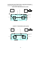
The next thing to do is establish which switching system is employed. Remember
that all your interface has to do is duplicate the action of the factory door lock
switch(es)
, even if they are located in the door lock actuators themselves. Using
your multimeter, find out what is happening on the central locking wires. Then test
which wires you think are the correct wires using a 1A fused wire for negative or
positive switching
. That way if you’ve got the wrong wires, all you will do is blow the
fuse and not the central locking control module. As a general rule, switching wires
are usually thin wires and motor wires are of thicker gauge.
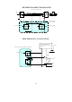
If the security system you are installin
g does not have on
-
board central locking
relays, but instead has low current negative output wires, take care when trying to
connect to some negative switching systems. Some cars, like the early Ford EA
Falcon, require a high current negative pulse to work
the central locking, so you will
require additional relays.
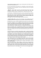
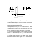
If you find it appears to be neither negative or positive, then it may be reverse
polarity, such as is found in Ford XE Fairmont. This will involve cutting the two
solenoid control wires and put
ting them through the normally closed contacts of the
alarm interface relays, wired so that the alarm will break the contact and feed a
positive pulse to the door solenoid for lock and unlock. The factory switch will then
operate the other doors. Some inst
allers refer to this as the “flow through method”.