
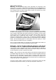
Specifications

20
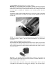
* Power wire
-
The wire that supplies power to the brain should be a dedicated wire
and should not be tapped onto for supply to any other sensors or relays. This will
avoid any voltage drop pr
oblems which may upset the microprocessor in the alarm
brain. All other accessories and relays should have their own power supply wire,
each with its’ own fuse.
Connection should be made at the battery or to any permanent power source in a
secure area. I
t should also have a dedicated fuse or circuit breaker with the correct
rating.
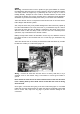
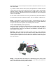
* 2 x Ground wire
-
Ground wires need to be as short as possible and should be
attached to two separate solid chassis points that are free of paint, dirt and grease.
Never con
nect the ground wires to the same chassis point.
Standards products use ‘normally open’ immobiliser relays and loss of a common
ground (if connected at same point) will cause the engine to stop whilst driving. 2
ground wires are therefore supplied to reduc
e this possibility.
A good ground connection will measure less than 0.1 Ohm. Metal supports under
the dash are sometimes isolated from the body of the vehicle with nylon or plastic
washers, as can be steering columns. Just because it’s metal doesn’t mean
it’s a
true ground. Always test with a multimeter. Always use star washers to ensure good
contact.
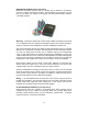
* Ignition sense wire
-
It is important that you find a “true” ignition source, i.e. one
that stays at 12 volts when the ignition is on and when the engine
is cranking, as
apposed to accessory wires which will drop off while the vehicle is in starting mode.
The ignition wire is usually found at the ignition switch harness.
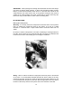
* Starter immobiliser wire
-
Whilst the starter wire can also be found at the ignitio
n
switch harness, it is recommended that you connect the alarm starter immobiliser
wires at a different location as this is the first place a potential thief is going to look
to hot wire a vehicle.
When testing to find the starter wire it will only have 1
2 volts on it when the key is
turned to the starting position and have 0 volts when the key is in the run or off
positions. Be aware though, that automatic vehicles may have what appears to be
two start wires, the second being the start inhibit wire from t
he transmission lever
switch. So when you have found what appears to be the start wire, cut the wire and
try to start the vehicle. If the vehicle still starts then rejoin the wire and find the
correct one.
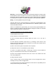
* Other engine immobiliser wires
-
As the Austral
ian/New Zealand Standard
requires at least two independent electrical means of preventing movement of the
vehicle under its own power, another circuit as well as the starter motor circuit
needs to be considered. Options include fuel pump circuit or the ign
ition circuit (or
diesel engine glow plug circuit), or transmission lock out solenoid.
The 2003
Installation Standard requires that the 2 immobile cuts are at least 300mm
apart from each other.
Vehicles with catalytic converters should never have the ignit
ion system
immobilised without the fuel system also being immobilised. Failure to disable the
fuel system could result in unburnt fuel entering the catalytic converter and cause
extensive damage.