
VFI Series User's Manual


VFI33 Vent Free Gas Fireplace System
20
20307670
RED
RED
RED
RED
RED
BLACK
D/C POWER
GREEN
GROUND
BROWN
BLACK
BLACK
ORANGE
YELLOW
BLACK
BLACK
RED
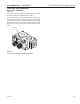
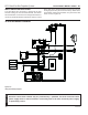
CAUTION
Electrical connections should only be performed by a qualifi ed, licensed electrician. Main
power supply must be turned off before connecting fans to the main electrical power supply
or performing service.
Figure 22 –
IPI System Wiring Diagram
IPI SYSTEM WIRING DIAGRAM
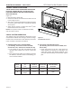
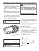
ELECTRICAL INSTALLATION – IPI
WALL SWITCH INSTALLATION
The wall switch wire connection is located off the wire
harness coming out of the IPI Control Board. The label is
wired 'wall switch'. Connect the low voltage switch wires to
the two (2) terminals labeled "wall switch" from the control
board. Run wire to desired location on wall. Up to 50 feet
of 18 gauge wire may be used if necessary. Attach wires
to wall switch. Mount the wall switch in a junction box and
screw on cover. Figure 22