
VFI Series User's Manual


VFI33 Vent Free Gas Fireplace System
20307670
19
CHECK GAS PRESSURE – IPI
1. Check gas type. The gas supply must be the same as
stated on the appliance’s rating decal. If the gas supply
is different from the fi replace, STOP! Do not install the
appliance. Contact your dealer immediately.
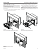
2. To facilitate easier installation, a 18" (610 mm) fl ex line
with manual shut-off valve has been provided with this
appliance. Install and attach 1/2" gas line onto shut-off
valve.
3. After completing gas line connection, purge air from
gas line and test all gas joints from the gas meter to the
fi replace for leaks. Use a solution of 50/50 water and
soap solution or a gas sniffer.
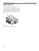
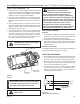
4. To check gas pressures at valve, turn captured screw
counter clockwise 2 or 3 turns and then place tubing
to pressure gauge over test point. Turn unit to high.
Figure 20. After taking pressure reading, be sure and
turn captured screw clockwise fi rmly to reseal. Do not
over torque. Check test points for gas leaks.
ELECTRICAL WIRING
General
1. This fi replace is equipped with an IPI control valve which
operates on 6 volts. The 6 volt DC adapter plugs into
the fi replace junction box A/C power supply.
2. The IPI system can also be operated without A/C power.
The system can run on four (4) “AA” batteries using the
optional battery backup for approximately six (6) months
under normal use.
Optional Accessories
This fi replace may be used with a wall switch, wall mounted
thermostat or IPI hand held remote control.
JUNCTION BOX WIRING
1. This should be done before framing the fi replace. Wire
the receptacle into an electrical circuit. Wire with mini-
mum 60° C wire in accordance with prevailing codes.
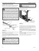
2. Remove the external junction box cover by removing
the screw from the side of the outside fi rebox wall.
Junction box was installed at the factory.
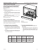
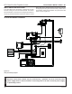
3. The junction box cover has a factory installed “romex”
style strain relief connector. After connecting the wires,
route the wire leads through this connector. Refer to
the wiring diagram in Figure 21.
CAUTION
Label all wires before disconnecting when
servicing controls. Wiring errors can cause
improper and dangerous operation.
Figure 20 –
IPI Valve
Pressure Inlet
Pilot Adjust-
ment Screw
Pressure
Outlet
FP3034
GAS PRESSURE & ELECTRICAL INSTALLATION — IPI
WARNING: Do NOT use open fl ame
to check for gas leaks.
WARNING: Electrical connections
should only be performed by a
qualifi ed, licensed electrician. Main
power must be off when connecting to
main electrical power supply or performing
service. All wiring shall be in compliance with
all local, city and state codes. The appliance,
when installed, must be electrically grounded
in accordance with local codes or in the
absence of local codes, with the National
Electrical Code ANSI/NFPA 70 (latest edition)
and Canadian Electrical Code, CSA C22.1.
Figure 21 –
Junction Box Wiring Diagram
Junction Box
Factory Supplied
Not Supplied
120V AC
60Hz
WARNING: Do NOT connect to a
110V circuit.