
Operating instructions


18
WARNING
Connecting directly to an unregulated propane/L.P.G. tank can cause an
explosion.
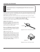
The heater gas inlet connection is 3/8" NPT at the valve, inlet on the left side facing the heater. If a right
side connection is required, the connecting pipe may be led under the rear of the gas log heater at the
left hand side for connection to the inlet.
When tightening up the joint to the valve, hold the valve securely with a wrench to prevent movement.
Test all gas joints from the gas meter to the heater valve for leaks using a gas analyzer or soap and water
solution after completing connection. DO NOT USE AN OPEN FLAME.
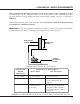
Check the gas pressure with the appliance burning and the control set to HIGH.
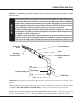
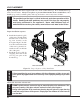
Manual Control (Figure 13)
Test Plug
Figure 13: Pressure Test Point Location
The pressure regulator is preset and locked to
discourage tampering. If the pressure is not as
specified, replace the regulator with the correct
part from the parts list in this manual.
Remove 1/8" NPT plug, located on side of regu-
lator body. Install fitting and tubing to pressure
gauge. After taking pressure reading, re-install test
plug. Check for gas leaks.
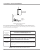
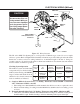
Millivolt Control (Figure 14)
The valve regulator controls the burner pressure
which should be checked at the pressure test point.
Turn captured screw counter clockwise 2 or 3 turns
and then place tubing to pressure gauge over test
point (Use test point "A" closest to control knob).
After taking pressure reading, be sure and turn cap-
tured screw clockwise firmly to re-seal. Do not
over torque. Check for gas leaks.
Test Port
Figure 14: Pressure Test Point Location
CHECKING GAS PRESSURE