
Manual

4 Nov 26 2012 AJW Rev 0.92
2. INSTALLATION
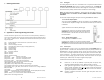
The F2A1X Frequency to Analog module is housed in a DIN Rail mountable ABS enclosure
112 x 100 x 23 mm (4.4 x 3.9 x 1 inches). There are screw terminal connections on both
ends of the unit. The module snaps onto a standard DIN Rail by clipping the non-metallic
“hook” at the base of the module into one edge of the rail then pushing the module home
allowing the metal spring clip to secure the module. The module is removed by inserting a
screwdriver into the exposed metal tab and leveraging this tab outwards while lifting the
module away from the rail.
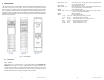
Fig 2.1 – F2A3X Module
2.1. Connections
2.1.1. Power
Power to the unit is connected to the 4 way terminal block marked ANALOG OUT
POWER IN. Refer to Figure 2.1 above – Right Side view. Note that these inputs are
polarity sensitive. Connect a DC supply of 12 to 24Vdc (with a 150mA source capacity)
into the two right hand terminals ensuring that the positive wire goes to the +
terminal and the common or negative wire goes to the – terminal.
Left Side Right Side Top View
9 Nov 26 2012 AJW Rev 0.92
@DAC1/FSCAL = xxx.xx Set the Reading value that the Analog output will output Full Scale
(5V or 20mA). Depends on TYPE
@DAC1/0SCAL Show Analog Out Zero Scale
@DAC1/0SCAL = xxx.xx Set the Reading value that the Analog output will output Zero Scale
(0V or 4mA). Depends on TYPE (Default is 0.00)
@DISPR Show Display Update Rate
@DISPR = HALF or 1_SEC or 1.5_S. This sets the maximum display update rate to one half a second, 1
second or 1 ½ seconds between updates.
@SERNO Show Serial Number
@SET1 Settings for Setpoint (Alarm)
STYPE OFF, HI, LO Select the Alarm type as High, Low or Off
LATCH NO, YES Select whether the Alarm is latching
LOC NO, YES Select whether the Alarm has a low level lockout.
FAILS NO, YES Select whether the Alarm is fail safe.
SETPT xxxxxx Enter the setpoint xxxxx=value.
DEADB xxxxxx Enter the dead band xxxx = value.