
User Manual

Section 3 – Installation
I. Page 14 1/06/2012 REV 1.10.2
3.1.6 Part Numbering
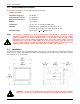
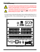
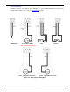
The part number for the recorder is in the format as follows (See Fig 3.0 below for option location):
DC6 –A –B –C –D –E –F –G where each of the letters A through G has a meaning as follows:
A Input Power: 1 - 100 to 240Vac 50/60Hz with cable and plug (Default - shown below)
2 - 18 – 30Vdc with Screw Terminals
3 - 100 to 240 Vac 50/60Hz with Screw Terminals
B Input Channels: 06 – 6 Channels of Analog input (single row of connectors – default)
12 - 12 Channels of Analog input (dual row of connectors)
C Output Options: 0 – None (Blank panel covers hole.)
1 - 6 Form A relay contacts 0.5A @ 200Vdc, 2 Control Inputs
2 - 12 Form A relay contacts 0.5A @ 200Vdc, 2 Control Inputs. (Shown below)
D Serial Comms: 0 – None (Blank panel covers hole.)
1 – RS232/RS485 (9 Pin D sub) Serial Port (shown below)
E Transmit Power: 0 – None (Blank panel covers hole.)
1 – 24Vdc 100mA isolated power output
F Int. Memory: 1 – 512 Megabyte SD Card
2 – 1 Gigabyte SD Card
3 – 2 Gigabyte SD Card
G FDA Compliance: 0 – Standard Unit
1 – FDA 21CFR11 Compliant Unit
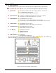
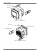
The unit shown below in rear view has the part number DC6 –1–06–2–1–1–1–0. (The additional 6
channels as would be in a 12 channel input recorder are shown grayed out).
Figure 3-0 Rear Panel showing ordering options
100 – 240 Vac 35VA