70 PNT Series Modbus Plus Communication Adapters for Momentum User Guide 31002940.0000 31002940 870 USE 103 00 Version 2.
870 USE 103 00 May 2001
Table of Contents About the Book . . . . . . . . . . . . . . . . . . . . . . . . . . . . . . . . . . . . . . . 5 Chapter 1 Introduction. . . . . . . . . . . . . . . . . . . . . . . . . . . . . . . . . . . . . . . . . . 7 At a Glance . . . . . . . . . . . . . . . . . . . . . . . . . . . . . . . . . . . . . . . . . . . . . . . . . . . . . . 7 Product Overview . . . . . . . . . . . . . . . . . . . . . . . . . . . . . . . . . . . . . . . . . . . . . . . . . 8 Status Indicators . . . . . . . . . . . . . . . .
870 USE 103 00 May 2001
About the Book At a Glance Document Scope This manual describes the functionality of the 170 PNT Series Modbus Plus Communication Adapters. The following information is an introduction to this manual: Function: The Modbus Plus Communication Adapters can be connected to any Momentum I/O base to create a functional I/O module. The adapters provide direct connection to the Modbus Plus network, enabling a programmable controller to communicate with field devices wired to the I/O base terminals.
Product Related Warnings Schneider Electric assumes no responsibility for any errors that may appear in this document. If you have any suggestions for improvements or amendments or have found errors in this publication, please notify us. No part of this document may be reproduced in any form or by any means, electronic or mechanical, including photocopying, without express written permission of the Publisher, Schneider Electric. User Comments We welcome your comments about this document.
Introduction 1 At a Glance Purpose This chapter gives an overview of the Momentum Modbus Plus Communication Adapter models 170 PNT 110 20 and 170 PNT 160 20 and describes their status indicators, address switches, ports and cabling.
Introduction Product Overview Overview This section provides an overview of the features and function of the Momentum Modbus Plus Communication Adapters. Function The Modbus Plus Communication Adapters can be connected to any Momentum I/ O base to create a functional I/O module. The adapters provide direct connection to the Modbus Plus network, enabling a programmable controller to communicate with field devices wired to the I/O base terminals.
Introduction Environmental Specification 870 USE 103 00 May 2001 The adapter conforms to the environmental specification for the I/O base upon which it is mounted. For further information refer to the Momentum I/O Bases User Manual, part number 870 USE 002 00.
Introduction Status Indicators Overview This section describes the status indicators for each model, gives a diagram of the indicators, and explains how to interpret the indicator patterns. Indicators Each model has a front panel indicator showing its network communication status. The dual-cable model has two additional indicators which identify communication errors on the two cable paths.
Introduction Modbus Plus Channel Error Indicators 870 USE 103 00 May 2001 Model 170 PNT 160 20 displays the following error indicator patterns: Indicator (Red) Status Channel A Error Communications error at network port A. Channel B Error Communications error at network port B.
Introduction Address Switches Overview This section describes the address switches and explains how to use them to set the module address. Two Rotary Switches Each Modbus Plus Communication Adapter has two rotary switches on the lower left portion of the front panel. These switches are used to set the Modbus Plus node address.
Introduction Example of Node Address Assignment The figure below shows typical address assignments for a network with one controller and four communication adapters.
Introduction Setting the Switches The figure below illustrates how to set a Modbus Plus Node Address. Do not install any adapter unless you have set its Modbus PLus address for your application. MB+ ACT ERROR A B 9 0 1 8 2 7 3 X10 4 5 6 9 0 1 8 2 7 3 4 X1 5 6 X10 9 0 1 8 2 7 3 5 6 9 4 X1 0 1 8 2 See your network administator to get the node address for each adapter. 7 3 Node Upper Address Switch 1... 9 0 10... 19 1 20... 29 2 30... 39 3 40... 49 4 50... 59 5 60...
Introduction Ports and Cabling Overview This section provides information about ports and cabling for the Momentum Modbus Plus Communication Adapters. Ports Model 170 PNT 110 20 has one Modbus Plus port for connection to a network with a single trunk cable. Model 170 PNT 160 20 has two ports for connection to either a single-cable or dualcable network. Cabling 870 USE 103 00 May 2001 Network port connections are compatible with standard Modbus Plus drop cables.
Introduction 16 870 USE 103 00 May 2001
Assembling a Communications Adapter and I/O Base 2 At a Glance Purpose This chapter explains how a Communication Adapter connects with an I/O base, how to assemble a module, and how to label the assembled module. It also includes a procedure for disassembling a module.
Assembling Adapter and I/O Base Connections Between the Adapter and I/O Base Overview This section explains the connections between a Communication Adapter and an I/ O base.
Assembling Adapter and I/O Base Assembling the I/O Base and the Adapter Overview This section contains safety precautions for handling components and a procedure for assembling an I/O base and an adapter. CAUTION ADAPTER MAY BE DAMAGED BY STATIC ELECTRICITY Use proper ESD procedures when handling the adapter, and do not touch the internal elements. The adapter’s electrical elements are sensitive to static electricity. Failure to observe this precaution can result in injury or equipment damage.
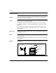
Assembling Adapter and I/O Base Step 20 Action 3 Align the two plastic snap extensions on the Adapter with the slots on the sides of the I/O base. The ATI connectors will automatically line up when the units are in this position. The two devices should be oriented such that their communication ports are facing out on the back side of the assembly. 4 Using the sidewalls of the I/O base as guides, carefully push the Adapter onto the base until the extensions snap into place.
Assembling Adapter and I/O Base Labeling the Assembled Module Overview A front panel label is supplied with each I/O base. The user should fill out the label and affix it to the front panel of the adapter. What Goes on the Label? The user should fill out the label to identify the field wiring connections and application of the I/O base terminals. Example of a Label A fill-in label is illustrated in the diagram below.
Assembling Adapter and I/O Base Disassembling an Adapter from an I/O Base Overview This section contains safety precautions and a procedure for disassembling an adapter from an I/O base. CAUTION ELECTRICAL CIRCUITRY MAY BE EXPOSED Before removing an adapter from the base, disconnect the wiring connectors. Make sure that the I/O base is not under power when it does not have a Momentum adapter mounted on it. Failure to observe this precaution can result in injury or equipment damage.
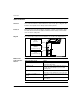
Assembling Adapter and I/O Base Step 870 USE 103 00 May 2001 Action 3 Use a screwdriver to push the clips on both sides of the adapter inward, as shown in the illustration below. 4 Lift off the adapter.
Assembling Adapter and I/O Base 24 870 USE 103 00 May 2001
Using Modbus Plus for Distributed I/O Servicing 3 At a Glance Purpose This chapter explains how best to configure a network for efficient servicing of distributed I/O.
Modbus Plus for DIO Servicing Strategies for Distributed I/O Servicing Overview Modbus Plus networks can be used to service multi-purpose control applications, or they can be organized for the most efficient servicing of distributed I/O devices. This section compares the two approaches. Network Function In multi-purpose control applications, the network is designed to allow communication between in programmable controllers, operator interfaces, and other kinds of devices.
Modbus Plus for DIO Servicing Network Configuration Overview This section contains guidelines for configuring a Modbus Plus network for distributed I/O servicing. Limit Types of Devices on Network To ensure deterministic timing, the network should consist of just one programmable controller node and the required group of I/O nodes. Maximum Configuration The table below summarizes the Modbus Plus network’s maximum configuration for a distributed I/O application consisting of Momentum products.
Modbus Plus for DIO Servicing Modbus Plus Network Layouts Overview This section provides two examples of Modbus Plus network layouts using communication adapters in a distributed I/O control application. Note that only one programmable controller and the required I/O nodes are present in this kind of application. Single Cable Example The figure below illustrates a single cable configuration.
Modbus Plus for DIO Servicing Dual Cable Example The example below illustrates a dual cable configuration.
Modbus Plus for DIO Servicing 30 870 USE 103 00 May 2001
How Communication Adapters Handle Messages 4 At a Glance Purpose This chapter describes how messages are defined in the application and how messages are transacted on the network.
Communication Adapter Message Handling How Messages Are Defined in the Application Overview This section describes where and how messages are defined in the application. Peer Cop Table The user defines I/O message transactions in the Peer Cop table of the controller. Entries to the table are made using panel software, such as Schneider’s Concept or Modsoft software. The Peer Cop table specifies the controller registers that are to be used for the I/O data storage.
Communication Adapter Message Handling How Messages are Transacted Overview This section explains how a Communication Adapter relays information between its I/O base and a programmable controller. The Right to Transmit A token frame is passed from node to node in a rotating address sequence. The node currently holding the token has the sole right to transmit. All other nodes monitor the network and extract messages addressed to them.
Communication Adapter Message Handling 34 870 USE 103 00 May 2001
Communication Access Registers 5 At a Glance Purpose This chapter describes the three types of communication access registers.
Communication Access Registers Overview of Register Types Purpose Each adapter contains three groups of internal registers that enable the application program to communicate with the I/O base module. This section describes the three register types, their functions and how they are accessed.
Communication Access Registers Diagram of Register Types The three groups of internal registers are illustrated in the diagram below.
Communication Access Registers Data Registers Overview This section describes the use, field length and access to data registers. Use Starting reference 40001 (hex) is used to address input data from field inputs and output data to field outputs. Field Length The data field length is determined by the specific I/O base. Access This reference is the only one that is accessible through Peer Cop data transfers. All other registers can be accessed using MSTR blocks.
Communication Access Registers Configuration Registers Overview This section describes the function and parameters for module timeout and module ownership registers. Module Timeout Register Function The module timeout register specifies the amount of time that outputs will be held in their current state, if they are not updated by a new Modbus Plus Write command. If the module’s holdup time expires before a new write command is received, all outputs are set to logical 0 (zero).
Communication Access Registers Note that this 60-second Write Privilege timer is separate from the Outputs Holdup timer, and applies only to the write privilege. Any node may read the input data or status information from the adapter. The 60-second time is a fixed value and is not accessible to the application. Module Ownership Registers Parameters 40 The table below contains parameters for module ownership registers.
Communication Access Registers Status Registers Overview This section describes the function and parameters of the module status block and the ASCII header block. Module Status Block Function These registers provide information about the module’s revision level and current operating parameters. Module Status Block Parameters The module status block layout is described in the table below. The registers can be read, but cannot be written into.
Communication Access Registers ASCII Header Block Function These registers contain an ASCII text description of the module. ASCII Header Block Parameters The block length depends upon the type of I/O base to which the adapter is connected. The maximum length is 64 bytes of ASCII characters, corresponding to a length of 8...32 words as specified in word 6 of the module status block (at reference 4F806). The registers can be read, but cannot be written into.
Communication Access Registers Examples of an ASCII Header Block The figure below shows two examples of an ASCII Header Block.
Communication Access Registers 44 870 USE 103 00 May 2001