
User guide
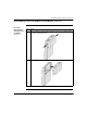

Assembling TSX Momentum Components
66
870 USE 101 00 V.2.2
Mounting the Assembled Adapters on the I/O Base,
Continued
Procedure:
Mounting the
Assembled
Adapters on an
I/O Base,
Continued
Step Action
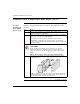
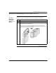
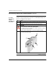
3 Push the assembled adapters onto the base, gently pressing the locking tabs
inward.
Snap #1 shown in the illustration below will not align properly with the mating slot in
the I/O base unless the Option Adapter is placed straight onto the base. Do not
attach just one latch and rotate the Option Adapter onto the I/O base.
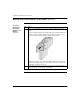
Result:
The locking tabs on each side of the Option Adapter slide inside the I/O
base and out through the locking slot. The 12-pin ATI connectors on the two units
are mated to each other in the process.
4 Apply slight pressure to the top of the stirrup on the back of the Option Adapter so
that it snaps into place on the bottom of the I/O base.