
User guide


Option Adapters
870 USE 101 00 V.2.2
49
Front Panel Components,
Continued
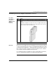
Modbus Plus
Address
Switches
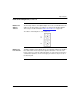
The two rotary switches on the Option Adapter are used to set a Modbus Plus node
address for the CPU module. The switches are shown in the following diagram.
Their usage is described in detail in Modbus Plus Addresses
on page 132.
The switches in this diagram are set to address 14.
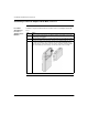
Modbus Plus
Ports A and B
This Option Adapter has two Modbus Plus ports. Redundant cabling on the Modbus
Plus network offers increased protection against cable faults or excessive noise
bursts on either one of the two cable paths. When one of the channels experiences
communication problems, error-free messaging can continue to be processed on
the alternate path.