
User guide


Using the I/OBus Port
870 USE 101 00 V.2.2
113
I/OBus Accessories,
Continued
Interbus Cable
Pinouts
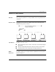
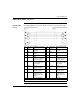
The following diagram shows how to wire the connectors of the remote bus cable:
Pin Wire Color Outgoing Connection Pin Wire Color Ingoing Connection
1 Yellow DO
Data Out
1 Yellow DO
Data Out
2Gray DI
Data In
2Gray DI
Data In
3 Brown Common 3 Brown Common*
4 GND
Reference conductor,
fiber-optic adapter
4GND*
Reference conductor,
fiber-optic adapter
5 Vcc
Power-supply for fiber-
optic adapter
5 Vcc*
Power-supply for fiber-
optic adapter
6 Green DO_N
Data Out Negated
6 Green DO_N
Data Out Negated
7 Pink DI_N
Data In Negated
7 Pink DI_N
Data In Negated
8Vcc
Additional power
supply for fiber-optic
adapter
8 Vcc*
Additional power
supply for fiber-optic
adapter
9 Plug identification 9 Not used
* Physically isolated