Contents Momentum Contents b Introduction to Momentum . . . . . . . . . . . . . . . . . . . . . . . . . . . . . . . . . . . . . . . . . . . . . . . . . . . . . . . . . . . . . b Discrete I/O Bases Selection Guide. . . . . . . . . . . . . . . . . . . . . . . . . . . . . . . . . . . . . . . . . . . . . . . . . . . . b Discrete I/O bases . . . . . . . . . . . . . . . . . . . . . . . . . . . . . . . . . . . . . . . . . . . . . . . . . . . . . . . . . . . . . . . . . . . . .
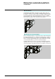
Momentum automation platform Introduction A modular concept with four easy pieces The Momentum system comprises 4 fundamental components that easily snap together in various combinations to form versatile control systems or sub-systems.
Momentum automation platform 0 Introduction Momentum I/O bases Specialized Momentum I/O Bases support the rest of the control system. The Communication Adapters, Processor Adapters and Option Adapters all snap onto the I/O Bases. A selection of I/O base modules are available, including analog I/O, discrete I/O, multi-function analog and bi-directional discrete bases.
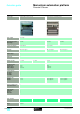
Selection guide Momentum automation platform 0 Discrete I/O bases Product type Input modules for direct current Type of signal True high Operating voltage and Input voltage 24 VDC 120 VAC Current consumption max. 250 mA max.
0 Output modules for direct current Output modules for alternating current 24 VDC 120 VAC 230 VAC max. 250 mA max. 125 mA max. 65 mA 24 VDC 120 VAC 230 VAC Solid state switch Triac – 2 x 8 out 2 x 16 out None None 500 VAC 0.5 A 4A 8A 2 x 4 out 2 x 8 out 2 x 4 out 2 x 8 out 0.5 A 4A 8A 2A 4A 8A 0.5 A 4A 8A 170 ADO 540 50 170 ADO 730 50 170 ADO 740 50 None None 1780 VAC 0.5 A 8A 16 A 2A 4A 8A < 0.1 ms < 0.1 ms max. 1/2 x 1/f max.
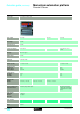
Selection guide (continued) Momentum automation platform 0 Discrete I/O bases Product type I/O modules for direct current Type of signal True high Input voltage 24 VDC Operating voltage 24 VDC Current consumption max.
0 Output modules for direct current Output modules for alternating current True high 24…230 VAC 20…115 VDC 120 VAC 120 VAC max. 180 mA max. 250 mA max. 160 mA IEC 1131 Type 1+, monitored IEC 1131 Type 1+ IEC 1131 Type 2 24…230 VAC or 20…115 VDC 120…132 VAC Relay (normally open) Triac 1 x 16 In, 1 x 8 Out and 1 x 4 Out 1 x 10 In, 2 x 4 Out 1 x 10 In, 1 x 8 Out None None 500 VAC None None 500 VAC 0.5 A 4 A group 1, 2 A group 2 6A 2 A ohmic load 8 A ohmic load 16 A ohmic load 0.
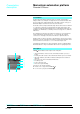
Momentum automation platform Presentation, description Discrete I/O Bases Presentation The Momentum Automation Platform products are modular. Communication Adapters and Processor Adapters are designed to work as functional modules when they are snapped onto a Momentum I/O base. An I/O base requires some type of Momentum Adapter assembled on it before it can be functional. The I/O bases fit into compact standard housings that can be mounted on a DIN rail or on panels in a cabinet.
Momentum automation platform Characteristics 0 Discrete I/O Bases Characteristics of discrete input bases Type of input base unit Number of inputs 170 ADI 340 00 170 ADI 350 00 170 ADI 540 50 1 x 16 2 x 16 2x8 170 ADI 740 50 Input voltage V 24 DC 120 AC 230 AC Operating voltage V 24 DC Internal current mA 250 (@ 24 VDC) 85…132 AC (@ 47…63 Hz) 125 (@ 120 VAC) 164…253 AC (@ 47…63 Hz) – ON voltage OFF voltage ON V V V mA - 3…30 DC + 11…30 DC - 3…+ 5 DC 2.
Momentum automation platform Characteristics (continued) Discrete I/O Bases Characteristics of discrete I/O bases Type of base unit 170 ADM 350 10 170 ADM 350 11 170 ADM 350 15 170 ADM 370 10 170 ADM 390 10 Number of inputs 1 x 16 4x4 1 x 16 Number of outputs 2x8 2x4 1 x 8 and 1 x 4 250 @ 24 VDC (plus current for sensors) 180 @ 24 VDC Operating voltage VDC 24 Internal current mA 250 @ 24 VDC VDC 24 Inputs Voltage Type of signal True low True high Voltage at 1 VDC + 11…+ 30 - 3…
Momentum automation platform Characteristics (continued) 0 Discrete I/O Bases Characteristics of discrete I/O bases (continued) Type of base unit 170 ADM 390 30 Number of inputs 1 x 10 Number of outputs 2x4 170 ARM 370 30 Operating voltage V 24 DC 120 AC (47…63Hz) Internal current mA 250 (@ 24 VDC) 5 minimum load current VDC 24 Inputs Voltage True High Signal type Outputs On voltage minimum VDC + 11…+ 30 Off voltage maximum VDC - 3…+ 5 Input current mA 2.5 minimum On, 1.
Momentum automation platform Characteristics (continued) Discrete I/O Bases Characteristics of discrete I/O bases (continued) Type of base unit 170 ADM 690 51 Number of inputs 1 x 10 Number of outputs 1x8 Operating voltage VAC 120 (47…63 Hz) Internal current mA 160 (@ 120 VAC) VAC 120 Inputs Voltage True high Signal type Outputs On voltage minimum VAC 74 Off voltage maximum VAC 20 Input current mA 6.0 minimum at state 1, 2.6 maximum at state 0 Input voltage range VAC 74...
Momentum automation platform References 0 Discrete I/O Bases Discrete input bases Type of current Input voltage DC 24 V AC 170 ADI pp0 p0 Modularity (no. of points) Conformity EC 1131-2 Reference Weight kg 16 (1 x 16) Type 1 170 ADI 340 00 0.190 32 (2 x 16) Type 1 170 ADI 350 00 0.200 100…120 V 16 (2 x 8) Type 2 170 ADI 540 50 0.284 200…240 V 16 (2 x 8) Type 2 170 ADI 740 50 0.
References (continued), dimensions, mounting Momentum automation platform 0 Discrete I/O Bases References Accessories Description 170 XTS 001 00 170 XTS 002 00 170 XTS 004 01 170 XTS 005 01 Composition Type of connection Reference Terminal blocks for Set of 3 connectors 1 Screw I/O base row connection Spring Bus Bar 3 rows Screw Spring 2 rows Screw Spring 1 row Screw Spring Cable grounding Used to connect – rail the cable shielding High vibration Kit containing 5 sets – environment clips of clips
Momentum automation platform Connections 0 170 ADI 340 00 Example of external wiring of 2, 3 and 4-wire sensors 170 ADI 350 00 Example of external wiring of 2 and 3-wire sensors 24 V 1 2 3 4 5 6 7 8 9 10 11 12 13 14 15 16 M– L + 1 315 mA fast-blow fuse 24 V Return 1 2 3 4 5 6 7 8 9 10 11 12 13 14 15 16 M – L + 1 1L+ 4 A max. 2 24 V Return 1L+ M– M– 3 M– 315 mA fast-blow fuse 1L+2 L+ 4 A max.
Momentum automation platform Connections (continued) 0 0 Discrete I/O Bases 170 ADO 340 00 Example of external wiring of 2 and 3-wire actuators 170 ADO 350 00 Example of external wiring of 2 and 3-wire actuators 24 V 1 1 315 mA fast-blow fuse 1 2 3 4 5 6 7 8 9 10 11 12 13 14 15 16 M– L+ 1 4 A max. 2 3 4 5 6 7 8 9 10 11 12 13 14 15 161L+ 2L+ fast-blow fuse 24 V Retour 24 V 2 4 A max. 1 2 3 4 5 6 7 8 9 10 11 12 13 14 15 16 1L+2L+ fast-blow fuse M – L+ 3 24Return V 4 A max.
Momentum automation platform Connections (continued) 0 Discrete I/O Bases 170 ADM 350 10/350 11/350 15 Example of external wiring of a 2-wire sensor/actuator Example of external wiring of a 3-wire actuator with wiring check 24 V 24 V 1 1 2 3 4 5 6 7 8 9 10 11 12 13 14 15 16 M – L+ 315 mA fast-blow fuse 24 V 1 315 mA fast-blow fuse 1 2 3 4 5 6 7 8 9 10 11 12 13 14 15 16 M– L+ 1 2 3 4 5 6 7 8 9 10 11 12 13 14 15 16 1L1 2 L+ 4 A max.
Momentum automation platform Connections (continued) 0 Discrete I/O Bases 170 ADM 370 10 Example of external wiring of 2 and 4-wire sensors/2-wire actuator Example of external wiring of 3-wire actuator with wiring check 24 V 1 2 3 1 2 3 4 5 6 7 8 9 10 11 12 13 14 15 16 M – L+ L+ L+ L+ L+ 24 V 24 V Return 1 8 A max. slow-blow fuse 2 1M– 2M– 8 A max. slow-blow fuse 3 2 3 4 5 6 7 8 9 10 11 12 13 14 15 16 1L+ 2L+ 1 4 A max.
Momentum automation platform Connections (continued) 0 Discrete I/O Bases 170 ADM 390 10 Example of external wiring of 2-wire sensor/actuator 170 ADM 390 30 Example of external wiring of 3 or 4 sensor/3-wire/actuator 24 V 1 200 mA fast-blow fuse 1 2 3 4 5 6 7 8 9 10 11 12 13 14 15 16 M– L+ 24 V 24 V Return 1 2 3 4 5 6 7 8 9 10 1 1L+ M – M– 1L+ M– L+ 315 mA fast-blow fuse Return L N 2 1 8 9 4 A max. 1L+ 2L+ fast-blow fuse 12 161L+ 2L1 4 A max. fast-blow fuse 1L+ 9 10 2 56 k 4 A max.
Selection guide Momentum automation platform 0 Analog I/O bases Application 24 VDC analog input bases Operating voltage 24 VDC Measurement range Inputs ± 5 V, ± 10 V, ± 20 mA 1-5 V, 4-20 mA Inputs ± 5 V, ± 10 V, 4-20 mA Inputs ± 25 mV, ± 100 mV, Temperature probe Pt 100, Pt 1000, Ni 100, Ni 1000 Thermocouple B, E, J, K, N, R, S, T Modularity Input channels Output channels 8 differential inputs – 16 single ended inputs – 4 differential inputs – Discrete I/O – – – Resolution 14 bits + sig
0 24 VDC analog output bases 24 VDC mixed I/O bases (analog/discrete) Inputs ± 5 V, ± 10 V, ± 20 mA 1-5 V, 4-20 mA Outputs ± 10 V, 0-20 mA Inputs 0…10 V Inputs - 10…+ 10 V Outputs 0…10 V Outputs - 10…+ 10 V – 4 outputs 4 differential inputs 2 outputs 6 inputs with common point 4 outputs with common point – 4 inputs 24 VDC 2 outputs 24 VDC/0.5 A 8 inputs 24 VDC 8 outputs 24 VDC/0.25 A 12 bits + sign Inputs: 12…14 bits (dep.
Momentum automation platform Presentation, description Analog I/O Bases Presentation The Momentum analog input bases enable acquisition of various analog values encountered in industrial applications, including: b b b b Standard high level (1-5 V, 4-20 mA, + 5 V, +10 V, + 20 mA). Low level (+ 25 mV, + 100 mV). Thermocouples (B, E, J, ...). Temperature probes (Ni ..., Pt ...). The analog output bases are used to control analog field devices such as various speed drives, proportional control valves, etc.
Momentum automation platform Characteristics 0 Analog I/O Bases Characteristics of analog input bases Type of base units 170 AAI 030 00 Number of inputs 1x8 LEDs Ready (green) Format of data Full 16 bits signed (two's complement) Differential ± 10 VDC ± 5 VDC 4…20 mA ± 20 mA 1 to 5 VDC > .1000 > .1000 250 250 >.1000 Error at 25 °C 0.27 % 0.21 % 0.27 % 0.32 % 0.13 % Error at 60 °C 0.32 % 0.26 % 0.38 % 0.41 % 0.
Momentum automation platform Characteristics (continued) Analog I/O Bases Characteristics of analog input bases Type of base units 170 AAI 140 00 170 AAI 520 40 Number of inputs 1 x 16 1 x 4 differential inputs Format of data Full 16 bits signed (2's complement) Protection Polarity inversion Base and actuators Error indication None Ranges ± 10 V ±5V 4…20 mA ± 25 mV ± 100 mV > 2200 > 2200 < 0.250 > 10000 > 10000 Error at 25 °C 0.15 % FS 0.15 % FS 0.
Momentum automation platform Characteristics (continued) 0 Analog I/O Bases Characteristics of analog output bases Type of base units 170 AAO 120 00 170 AAO 921 00 Number of outputs 1x4 Format of data Full 16 bits signed (2's complement) Protection Polarity inversion Base and actuators Ranges 0.6 maximum 1 minimum 0.6 maximum Capacitive load µF <1 Error at 25 °C % 0.2 PE 0.3 PE 0.2 PE 0.4 PE Error at 60 °C % 0.25 PE 0.4 PE 0.25 PE 0.
Momentum Automation Platform Characteristics (continued) Analog I/O Bases Characteristics of discrete and analog I/O bases Type of base unit 170 AMM 090 00 Number of inputs and outputs Operating voltage VDC 1 x 4 differential inputs 1 x 4 discrete inputs 1 x 2 analog outputs 1 x 2 discrete outputs 24 Internal current mA 200 typical (at 24 VDC), 350 maximum (at 24 VDC) Differential inputs 10 ms for all channels Conversion time Conversion error 25 °C 60 °C Resolution Conversion consistency Commo
Momentum automation platform Characteristics (continued) 0 Analog I/O Bases Characteristics of discrete and analog I/O bases (continued) Type of base units 170 ANR 120 90 Number of inputs and outputs 1 x 6 analog inputs 2 x 4 discrete inputs 1 x 4 analog outputs 1 x 8 discrete outputs Operating voltage VDC 24, range 19.2 to 30 VDC Internal current mA 400 @ 24 VDC W 14 bit 0 - 10 VDC Single-ended 0.75 ms maximum for 6 input channels 0.
Momentum automation platform References 0 Analog I/O Bases Analog input bases Type of inputs 12 bits + sign Number of channels 16 Ranges 15 bits + sign 4, differential Pt 100, Pt 1000, NI 100 170 AAI 520 40 thermocouples B, E, J, K, N, R, S, T 0.215 8, differential ± 5 V, ± 10 V, 1-5 V± 20 mA, 170 AAI 030 00 4-20 mA 0.215 Reference ± 5 V, ± 10 V, 4-20 mA 170 AAI 140 00 Weight kg 0.
References (continued), dimensions, mounting Momentum automation platform 0 Analog I/O Bases Accessories Description Terminal blocks Composition Type of connection Reference Set of 3 connectors 1 row 170 XTS 001 00 Bus Bar 170 XTS 002 00 3 rows 2 rows 1 row 170 XTS 004 01 Screw 170 XTS 001 00 Weight kg – Spring 170 XTS 002 00 – Screw 170 XTS 004 01 – Spring 170 XTS 003 01 – Screw 170 XTS 005 01 – Spring 170 XTS 008 01 – Screw 170 XTS 006 01 – Spring 170 XTS 007 01 – Cab
Momentum automation platform Connections 0 Analog I/O Bases 170 AAI 140 00 170 AAI 520 40 Example of external wiring of sensor 24 V Inl16+ Inl14+ Inl15+ 1 Inl11+ Inl12+ Inl13+ Inl1+ Inl2+ Inl3+ Inl4+ Inl5+ Inl6+ Inl7+ Inl8+ Inl9+ Inl10+ Example of external wiring of 2-wire sensor 1 Return + U – I + – + – Group of channels Group of channels Internal wiring Internal wiring 170 AAI 030 00 RTD4– IS4– InU4– RTD4+ InU4+ IS4+ RTD3– IS3– InU3– 500 mA M – L+ fast-blow fuse M– L+ +
Momentum automation platform Connections (continued) 0 Analog I/O Bases 170 AMM 090 00 Example of external wiring of 2-wire sensor Example of external wiring of 2-wire actuator 1 1 24 V I2 I3 I4 M– M– QV1 QI1 AGND O2 U4+ IS4 UI4– I4+ QV2 QI2 I1 U3+ IS3 UI3– I3+ AGND AGND AGND O1 U2+ IS2 3 UI2– I2+ I4 M– 5A M – 1L+ fast-blow fuse 2 U1+ IS1 I3 M– 325 mA M – L+ fast-blow fuse UI1– I1+ I2 O2 QV2 QI2 I1 AGND O1 AGND QV1 QI1 U4+ IS4 UI4– AGND U3+ IS3 UI3– I3+ 24 V Return 24 V
Selection guide Momentum automation platform 0 Specialty module I/O bases Product type High-speed counter Operating voltage 24 VDC Unique features 2 independent, high-speed (10 kHz-200 kHz) counters Modularity Input channels 6 (3 per counter) True High Inputs Output channels 4 (2 per counter) True High Outputs Input characteristics Counter inputs 5 VDC differential input, 200 kHz counter; 24 VDC single-end input, 10 kHz counter Discrete inputs Output characteristics Counter outputs Discrete
0 I/O with Modbus Master Base SERIPLEX Bus Interface 120 VAC 24 VDC RS 485 2- or 4-wire Modbus port SERIPLEX bus connection 6 True High Inputs Interface to bus input 3 True High Outputs Interface to bus output – – 1 group of 6 inputs (120 VAC @47 to 63 Hz): - voltage range, 0 to 132 VAC - response time, < 12.3 ms @ 60 Hz On to Off, < 12.5 ms @ 60 Hz Off to On SERIPLEX version 2 bus input devices supported @ 24 VDC bus voltage – – 3 solid state switching outputs: - on current, 0.
Momentum automation platform Presentation, description Momentum specialty module I/O bases Presentation The Momentum specialty module I/O bases provide support for unique applications that broaden the range of the Momentum offering. The specialty modules are : b a 2-channel, High-Speed Counter Module Base - 170 AEC 920 00. b a 120 VAC, 6-point Input/3-point Output Module Base with a Modbus Communication Port - 170 ADM 540 80.
Momentum automation platform Characteristics 0 Momentum specialty module I/O bases Characteristics Model No. Number of I/O Discrete inputs Counter 170 AEC 920 00 2 independant 170 ADM 540 80 – Inputs 2 x 3 discrete 1 x 6 discrete Outputs 2 x 2 discrete 1 x 3 discrete Operating voltage V 24 DC 120 AC @ 47 to 63 Hz Input range V - 3 to +30 DC 0-132 AC Input surge V 45 peak for 10 ms 200 AC for 1 cycle On mA 2.5 minimum 5.5 minimum Off mA 1.2 maximum 1.
Characteristics (continued), references Momentum automation platform 0 Momentum specialty module I/O bases Characteristics Model No.
Momentum automation platform Connections 0 Momentum specialty module I/O bases 170 AEC 920 00 A 2-encoder and input/output field wiring example Counter 1 A1+ B1+ Z1+ 01+ Counter 2 Counter control inputs A2+ B2+ Z2+ 02+ I1 I2 I3 I4 I5 I6 M- L+ 11 12 13 14 15 16 17 18 Fuse + 24 VDC Power for module - Return for module 1 1 2 3 4 5 6 7 8 9 10 Counter control outputs A1- B1- Z1- 01- A2- B2- Z2- 02- 1L+ 1L+ Q1 Q2 Q3 Q+ 1M- 1L+ 11 15 Fuse 2 1 2 3 4 5 6 7 8 9 10 1
Selection guide Momentum automation platform 0 Communication Adapters Applications Communication Adapters for Ethernet Communication Adapter for InterBus Bus and network type Ethernet InterBus-S Generation 3 Generation 4 Generation 4 Topology Physical interfce IEEE 802.
0 Momentum I/O modules on Profibus DP bus Momentum I/O modules on DeviceNet network Profibus DP DeviceNet EN 50170 standard – Master/Slave CSMA-CD 12 M bps…9.6 K bps depending on length 500 K bps Twisted pair Multidrop Multidrop, ring Multidrop No No 32 without repeater 126 with repeaters 64 1200 m 500 m with repeaters 170 DNT 110 00 170 LNT 710 00 48231/3 48233/3 Schneider Electric 0488Q-EN.
Selection guide (continued) Momentum automation platform 0 Communication Adapters Applications Communication Adapter for Modbus Plus Bus and network type Modbus Plus Topology Physical interfce Mobus Plus standard Method of access Rotating token Bit rate 1 M bps Medium Type Twisted pair Topology Multidrop Redundancy No Maximum number of Momentum devices Per segment 32 Overwall 64 (without repeaters) Maximum length 5 000 m with repeaters Type of communicating module 170 PNT 110 20
0 Momentum distributed I/O modules on Fipio bus for TSX Series 7 and April 5000 PLCs Momentum distributed I/O modules on Fipio bus for Premium PLCs Fipio Fip standard Bus managed by bus arbitrator 1 M bps Twisted pair Multidrop Yes No 128 170 NEF 160 21 Up to 5 000 m with repeater Up to 15 000 m with repeaters 170 FNT 110 00 170 FNT 110 01 48236/3 Schneider Electric 0488Q-EN.
Momentum automation platform Presentation, description Ethernet TCP/IP Communication Adapters Presentation The Model 170 ENT 110 00 and 170 ENT 110 01 Ethernet Communication Adapters for the Momentum I/O product line provide a direct connection to Ethernet-based networks for the entire family of Momentum I/O modules.
Momentum automation platform Characteristics, references 0 Ethernet TCP/IP Communication Adapters Characteristics 170 ENT 110 00 Model No Communication network Communication rate 170 ENT 110 01 Ethernet TCP/IP M bits/s 10 10 / 100 Number of nodes (devices) Unlimited with hubs and routers; 32 units point-to-point Media Twisted pair cable, 10Base-T Flash memory 128 K for IP parameter storage Distance m (ft) Twisted pair cable, 100Base-TX 100 (328) twisted pair cable without repeaters; unlimi
Momentum automation platform Presentation, description Momentum Modbus Plus communication adapters Presentation Modbus Plus Communication Adapters for the Momentum I/O product line can be plugged into any Momentum I/O base to create a functional I/O unit on the Modbus Plus bus, and to provide a direct connection to the Modbus Plus Network for the full family of Momentum I/O modules.
Momentum automation platform Presentation, description 0 Momentum Modbus Plus communication adapters Network topology Momentum I/O modules in a distributed control system 1 2 11 10 12 8 6 5 3 19 Momentum I/O modules with Modbus Plus double cable in a distributed and redundant control system DIO 13 14 15 16 17 18 4 9 7 1 140 NOM 212 00Quantum Modbus Plus Head-end Interface, redundant support, twisted pair cable 2 140 NOM 252 00Quantum Modbus Plus Head-end Interface, single-cable support
Description, characteristics Momentum automation platform Modbus Plus communication adapters Description 3 1 Each 170 PNT/NEF communication module comprises : 2 1 Three indicator lights (LEDs) : - MB + ACT indicator light (green) : module powered up or communicating. - ERR A indicator light (red) : communication error network A. - ERR B indicator light (red) : communication error network B. (for redundant model). 5 4 2 A 9-way male SUB-D connector for connecting to the Modbus Plus network.
Characteristics, references Momentum automation platform 0 Modbus Plus communication adapters References Description Communi cation modules for Momentum I/O subbases Connection Bus master PLC Non-redundant Premium Modbus Plus network Quantum 170 PNT 110 20/NEF 110 21 Redundant Modbus Plus network Description 170 PNT 160 20/NEF 160 21 170 PNT 110 20 Weight kg – Compact 984 170 NEF 110 21 – Quantum 170 PNT 160 20 Premium Compact 984 170 NEF 160 21 – Use Reference Reference – Weight kg Modb
Momentum automation platform Presentation, description 0 Fipio Communication Adapters Presentation The Fipio communication adapter can be plugged into a Momentum I/O base to create a functional I/O unit on theFipio bus, and to provide a direct connection to the Fipio Network for the full family of Momentum I/O modules.
Characteristics, references 0 Momentum automation platform 0 Fipio Communication Adapters Characteristics Type of module Bus manager PLC Structure Transmission 170 FNT 110 00 170 FNT 110 01 TSX Series 7, model 40 or April 5000 Premium Type Open industrial, conforming to the WorldFip standard Topology Devices connected using extension cable or tap-off cable Length meters 1,000 to 5,000 depending on the medium used Access method Producer/consumer principle, managed by a bus arbiter Bit rate
Momentum automation platform Presentation, description 0 InterBus-S Communication Adapters Presentation The Momentum InterBus-S Communication Adapter provides a direct connection to the InterBus-S Network for the full family of Momentum I/O modules. This connectivity enables Momentum I/O to be used in open architecture control systems that utilize either a programmable controller or industrial computer as the network master.
Momentum automation platform Characteristics, references 0 InterBus-S Communication Adapters Characteristics Model No.
Momentum automation platform Presentation, description 0 Profibus communication adapter Presentation The Model 170 DNT 110 00 Profibus DP Communication Adapter for the Momentum I/O product line provides a direct connection to the Profibus DP Communication Network for the full family of Momentum I/O modules.
Momentum automation platform Characteristics, references 0 Profibus communication adapter Characteristics Model No. 170 DNT 110 00 Communication rate 9.
Momentum automation platform Presentation, description 0 DeviceNet communication adapter Presentation The Model 170 LNT 710 00 DeviceNet Communication Adapter for the Momentum I/O product line provides a direct connection to the DeviceNet Communication Network for the full family of Momentum I/O modules.
Momentum automation platform Characteristics, references 0 DeviceNet communication adapter Characteristics Model No. 170 LNT 710 00 ODVA compliance Communication rates With ODVA Specification Release 2.
Selection guide Momentum automation platform 0 ConneXium industrial Ethernet Product type Hubs Technology Ethernet 10 Mbit/s Interfaces 4 10BASE-T ports 3 10BASE-T ports 2 10BASE-FL ports 4 100BASE-TX ports Connection Type Twisted pair cable Twisted pair cable and redundant fiber optic ring Twisted pair cable Type of connector Shielded RJ45 for 10BaseT Shielded RJ45 for 10BASE-T BFOC for 10BASE-FL Shielded RJ45 for 100BaseTX Terminal block 1 x 5-pin pluggable Operating voltage 18 to 3
0 Switches Transceivers Ethernet 10 Mbit/s and Fast Ethernet 100 Mbit/s Ethernet 10 Mbit/s Ethernet 100 Mbit/s 5 10BASE-T/100BASE-TX and 2 100BASE-TX ports 5 10BASE-T/100BASE-TX and 2 100BASE-FX ports 1 10BASE-T port and 1 10BASE-FL port 1 100BASE-TX port and 1 100BASE-FX port Twisted pair cable Twisted pair cable and redundant fiber optic ring Twisted pair cable and fiber optic Ethernet cable Shielded RJ45 for 10BaseT/100BaseTX Shielded RJ45 for 10BASE-T and 100BASE-TX; SC for 100BASE-FX Shi
Selection guide (continued) Momentum automation platform 0 ConneXium Ethernet cabling system Product type Optical cables Cable type Standard glass fiber optic Pre-assembled connector type MT/RJ-SC duplex Cable lenght(s) 5 m (16.4 ft) Radiation susceptibility No radiation along the cable Agency approvals Category 5 of cabling standard EIA/TIA-568; class D of IEC 11801/EN50173 Networks link – Operating power – Ports – Type of module 490 NOC 000 05 Pages 48190/6 0459Q_EN.
0 Electrical cables Shielded and foil twisted pair straight-through cable Bridges Shielded and foil twisted pair cross-over cable RJ45 (two per cable) 2, 5, 12, 40, 80 m 6.5, 16.4, 39.4, 131.2, 262.4 ft Modbus Plus to Ethernet Bridge Modbus to Ethernet Bridge – 5, 15, 40, 80 m 16.4, 49.2, 131.2, 262.4 ft – – UL and CSA (22.
Momentum automation platform Presentation 0 ConneXium industrial Ethernet Presentation As part of its Transparent Factory family of products, Schneider Electric offers a range of industrially hardened network hubs, switches, transceivers, bridges, and cables. These Ethernet-standard communication components enable you to integrate Ethernet solutions from the device level to the control network, and beyond to the corporate intranet.
Momentum automation platform Characteristics 0 ConneXium industrial Ethernet Mechanical construction Models Operating temperature 499 NEH 104 10 ° C (F) Relative humidity 499 NEH 141 00 499 NOH 105 10 0 to 60 (32 to 140) 10…95% (non-condensing) Dimensions W x H x D mm (in) 40 x 125 x 80 (1.58 x 4.92 x 3.15) 47 x 135 x 111 (1.85 x 5.31 x 4.37) 80 x 140 x 80 (3.15 x 5.51 x 3.15) Weight g (Lb) 520 (1.2) 240 (0.
Momentum automation platform Characteristics (continued) 0 ConneXium industrial Ethernet Mechanical construction Models Operating temperature 499 NES 171 00 ° C (F) Relative humidity 499 NOS 171 00 0 to 50 (32 to 122) 10…95% (non-condensing) Dimensions W x H x D mm (in) 105 x 130 x 105 (4.1 x 5.1 x 4.1) Weight g (Lb) 850 (1.87) 110 x 131 x 111 (4.3 x 5.2 x 4.4) Enclosure IP 20 Agency approvals and compliance cUL 1950; cUl 508; cUL 1604 Class 1, Div.
Momentum automation platform Characteristics (continued) 0 ConneXium industrial Ethernet Mechanical construction Models Operating temperature 499 NTR 100 10 ° C (F) Relative humidity 499 NTR 101 00 0 to 60 (32 to 140) 10…95% (non-condensing) Dimensions W x H x D mm (in) 40 x 134 x 80 (1.58 x 5.28 x 3.15) 47 x 135 x 111 (1.9 x 5.3 x 4.4) Weight g (Lb) 520 (1.2) 230 (0.51) Enclosure IP 30 IP 20 Agency approvals and compliance cUL 1950; FM 3810 Class 1, Div.
Momentum automation platform Characteristics (continued) 0 ConneXium industrial Ethernet Electrical cables Models 490 NTW 000 pp 490 NTC 000 pp Cable type Shielded and foil twisted pair straight-through cable Shielded and foil twisted pair crossed cord 2, 5, 12, 40, 80 (6.5,16.4, 39.4,131.2, 262.4) 5, 15, 40, 80 (16.4, 49.2,131.2, 262.4) Available cable length m (ft) Pre-assembled connector type RJ45 (two per cable) Agency approvals and compliance UL, CSA 22.
Momentum automation platform t References 0 ConneXium industrial Ethernet References Hubs 499 NEH 104 10 Description Reference Ethernet Hub 10 Mbps, 4 10BASE-T ports 499 NEH 104 10 Weight kg (lb) 0.520 (1.2) Ethernet Hub 10 Mbps, 3 10BASE-T ports, 2 10BASE-FL ports 499 NOH 105 10 0.900 (2) Ethernet Hub 100 Mbps, 4 100BASE-TX ports 499 NEH 141 00 0.520 (1.2) Ethernet Switch 10/100 Mbps, 7 100BASE-TX ports 499 NES 171 00 1.450 (3.
Selection guide Momentum automation platform 0 M1/M1E processor adapters Type M1 processor adapters RAM memory 64 K Flash memory 256 K 984 LL program memory 2.4 K 256 K 12 K IEC program memory 160 K Data memory 2K 4K Scan time 1 ms/K 0.63 ms/K 1 ms/K 0.
0 512 K 512 K 512 K for 171 CCC 980 20 1 MB for 171 CCC 980 30 512 K 512 Ko for 171 CCC 960 20 1 Mo for 171 CCC 960 30 –/200 K 240 K –/200 K 1 ms/K 0.3 ms/K 1 ms/K 0.
Momentum automation platform Presentation 0 M1/M1E processor adapters Presentation The Momentum M1/M1E processor adapters are based on the Modicon 984 family of products. You can mount these Adapters on Momentum I/O Bases to provide intelligence to the I/O. The Processor Adapter can quickly and independently solve logic, control its own local I/O (discrete or analog), and communicate to other control entities through one of a number of Momentum communication options.
Momentum automation platform Description, mounting 0 M1/M1E processor adapters 0 1 Description 2 A typical Momentum M1/M1E Processor Adapter consists of the following components. 1 2 3 4 3 Modbus or Ethernet Port connector Optional second port (Modbus or I/O bus) LED indicators Fill-in Label 4 Mounting A typical system, showing a model 171 CCS 760 00 Momentum M1/M1E Processor Adapter mounted on top of a Momentum I/O Base.
Momentum automation platform Characteristics 0 M1/M1E processor adapters Environment Type of processor Temperature 171 CCS 700 00 operating °C 0...60 storage °C - 40...85 Relative humidity 171 CCS 780 00 171 CCS 760 00 5...96% (non-condensing) Altitude Mechanical withstand (immunity) 171 CCS 700 10 m to vibrations 2000 (6,500 ft.) 57...150 Hz @ 1 G 10...57 Hz @ 0.075 mm d.a + 15 G peak, 11 ms, half sine wave to shocks Designed to meet UL, CE, CUL, FM Class 1 Div.
Momentum automation platform Characteristics (continued) 0 M1/M1E processor adapters Environment Type of processor Temperature 171 CCC 760 10 operating °C 0...60 storage °C - 40...85 Relative humidity 5...96% (non-condensing) m Altitude Mechanical withstand (immunity) 171 CCC 780 10 2000 (6,500 ft.) to vibrations 57...150 Hz @ 1 G 10...57 Hz @ 0.075 mm d.a to shocks + 15 G peak, 11 ms, half sine wave Designed to meet UL, CE, CUL, FM Class 1 Div.
Momentum automation platform Characteristics (continued) 0 M1/M1E processor adapters Environment Type of processor Temperature 171 CCC 960 20 operating °C 0...60 storage °C - 40...85 Relative humidity 5...96% (non-condensing) Altitude Mechanical withstand (immunity) 171 CCC 980 20 m 2000 (6,500 ft.) to vibrations 57...150 Hz @ 1 G 10...57 Hz @ 0.075 mm d.a to shocks + 15 G peak, 11 ms, half sine wave Designed to meet UL, CE, CUL, FM Class 1 Div.
Momentum automation platform Characteristics (continued) 0 M1/M1E processor adapters Environment Type of processor Temperature 171 CCC 960 30 operating °C 0...60 storage °C - 40...85 Relative humidity 5...96% (non-condensing) Altitude Mechanical withstand (immunity) 171 CCC 980 30 m 2000 (6,500 ft.) to vibrations 57...150 Hz @ 1 G 10...57 Hz @ 0.075 mm d.a to shocks + 15 G peak, 11 ms, half sine wave Designed to meet UL, CE, CUL, FM Class 1 Div.
References Momentum automation platform 0 M1/M1E processor adapters M1/M1E processor adapters RAM Memory 171 CCS 7p0 p0 Comm Port(s) Clock Speed Reference 64 K 1 Modbus 20 MHz 171 CCS 700 00 Weight kg (oz) 0.042(1.5) 64 K 1 Modbus 32 MHz 171 CCS 700 10 0.042(1.5) 64 K 2 Modbus 20 MHz 171 CCS 780 00 0.042(1.5) 256 K 1 Modbus, 1 I/O Bus 2 Modbus 32 MHz 171 CCS 760 00 0.042(1.5) 32 MHz 171 CCC 780 10 0.042(1.
Momentum automation platform Description, characteristics, references 0 M1 processor adapters Power supply An optional power supply, the 170 CPS 111 00, is available for the Momentum product family. Normally, power for controller, option, and communication modules is obtained from the power supply built into the I/O bases modules. However, the 170 CPS 111 00 provides a power solution for applications requiring conversion from 230 or 120 VAC to 24 VDC.
Selection guide Momentum automation platform 0 Option adapters Configuration Modbus Plus option adapters Communication network Modbus Plus Communication port(s) 1 Modbus Plus Comm port connector 9-pin D-shell Time-of-day clock On-board, + 13 sec/day accuracy Back-up batteries 2 user-replaceable AAA alkaline Voltage 5 VDC supplied by I/O base Operating temperature 0 ... 60°C Humidity 5 ... 95%, relative noncondensing Shock + 15 g peak, 11 ms, half-sine wave Vibration 10 ...
0 Serial option adapter General-purpose serial communications 1 software-selectable RS 232/RS 485 serial port 172 JNN 210 32 Schneider Electric 0494Q-FR.
Presentation Momentum automation platform 0 Option Adapters Presentation The Momentum Option Adapters, mounted on Momentum I/O Bases, can be used to enhance the capabilities of the Momentum Processor Adapters that mount on top of the Option Adapter, to fulfill a variety of roles.
Momentum automation platform Description 0 Option Adapters Description A typical Momentum Option Adapter consists of the following components : 1 2 9-pin D-shell connector(s) for Modbus Plus communications Batttery compartment 3 LED indicators 4 Address switches for Modbus Plus Mounting The Momentum Option Adapters provide the Processor Adapters with additional networking capabilities, a time-of-day clock, and a battery back-up.
Momentum automation platform Characteristics 0 Option Adapters Characteristics Model No 172 PNN 210 22 Time-of-day clock On-board, ± 13 s/day accuracy Batteries type Two user-replaceable AAA alkaline service life < 30 days from the time a battery-low indication is received, to actual battery failure @ 40½C maximum service life ambient temperature with the system continuously powered down.
References Momentum automation platform Option Adapters Modules 172 PNN 210 22 Description Reference Modbus Plus Option Adapters, Single Port 172 PNN 210 22 Weight kg (oz) 0.070 (2.5) Modbus Plus Option Adapters, Dual redundant Ports 172 PNN 260 22 0.070 (2.5) Serial Option Adapters, Single Serial Port 172 JNN 210 32 0.070 (2.
Presentation, PLC hardware configuration Momentum automation platform 0 Programming software Concept Presentation Concept is a software configuration and application programming tool for the Momentum automation platform. It is a Windows-based software that can be run on a standard personal computer. The configuration task can be carried out online (with the PC connected to the Momentum CPU) or offline (PC only).
Languages Momentum automation platform 0 Programming software Concept Concept provides an editor for each programming language. These editors contain custom menus and tool bars. You can select the editor to be used as you create each program segment. In addition to the language editors, Concept provides a data type editor, a variables editor and a reference data editor.
Languages Momentum automation platform 0 Programming software Concept Sequential function chart (SFC) With the IEC 1131-3 sequential function chart (SFC) language, you can define a series of SFC objects that comprise a control sequence. Steps, transitions and jumps in the sequence can be commented. You can place text freely within graphics. You can assign any number of actions to every step. A series of monitoring functions–e.g.
Data and variable editors, libraries Momentum automation platform 0 Programming software Concept Data type editor The data type editor defines new derived data types. Any elementary data types and derived data types already existing in a project can be used for defining new data types. With derived data types, various block parameters can be transferred as one set.
General features, references Momentum automation platform 0 Programming software ProWORX The ProWORX programming software is a full-featured, Modicon PLC programming software that is compatible with any Windows platform - 3.1/95/98/NT. A few of the new ProWORX features follow: Windows environment The familiar Windows-based programming environment means you spend less time learning how to do things, and more time being productive.
References (continued) Momentum automation platform 0 Programming software Concept and ProWORX References (suite) Concept upgrades Description Concept XL V. 2.2 to Concept XL V.2.
References (continued) Momentum automation platform 0 Programming software ProWORX ProWORX products Description User References Server 372 SPU 780 01 PSEV – 372 SPU 780 01 PSSV – Offline/Online Client 372 SPU 780 01 PDEV – Online Client 372 SPU 781 01 PONL – ProWORX NxT 32 Lite Offline/Online Client 372 SPU 710 01 PLDV – Legacy Product Upgrade to NX32 Client 372 SPU 784 01 LPUP – Multiuser Incremental Addition 372 SPU 780 01 SEAT – 3 Multi-user Client License 372 SPU 780 01 PST
References (continued) Momentum automation platform 0 Products Products Model number 042 703 583 043 513 781 110 XCA 203 00 110 XCA 203 01 110 XCA 203 02 110 XCA 204 00 110 XCA 204 01 110 XCA 204 02 110 XCA 282 01 110 XCA 282 02 110 XCA 282 03 170 AAI 030 00 170 AAI 140 00 170 AAI 520 40 170 AAO 120 00 170 AAO 921 00 170 ADI 340 00 170 ADI 350 00 170 ADI 540 50 170 ADI 740 50 170 ADM 350 10 170 ADM 350 11 170 ADM 350 15 170 ADM 370 10 170 ADM 390 10 170 ADM 390 30 170 ADM 540 80 170 ADM 690 51 170 ADO 3
References (continued) Momentum automation platform 0 Products Products (continued) Model number Description Category 170 BSM 016 00 170 CPS 111 00 170 DNT 110 00 170 ENT 110 00 24V DC Input Simulator - Switches 120/230 VAC Power Supply ProfiBus DP Communication Adapter Ethernet Communication Adapter (10 Mbps) Ethernet Communication Adapter, version 2 (10/100 Mbps) FIPIO Communication Adapter (V 1.0) FIPIO Communication Adapter (V 2.
References (continued) Momentum automation platform 0 Products Products (continued) Model number Description Category 170 XTS 060 00 170 XTS 100 00 Device Net Connector Universal Momentum Front Label Replacement (10) High Vibration Environment Clips (set of 5) M1 Processor Adapter, 512K RAM, RS232 and I/Obus Ports M1 Processor Adapter, 512K RAM, RS232 and RS485 Ports M1 Processor Adapter, 512K RAM, Ethernet and I/Obus Ports M1 Processor Adapter, 512K RAM,1M Flash Ethernet and I/Obus Ports ICE Exec M
References Momentum automation platform 0 User Documentation References Description Language Reference Momentum I/O Bases User Guide English 870 USE 002 00 Weight kg – French 870 USE 002 01 – German 870 USE 002 02 – Italian 870 USE 002 04 – Spanish 870 USE 002 03 – 870 USE 101 00 – 870 USE 101 01 – German 870 USE 101 02 – Italian 870 USE 101 04 – Spanish 870 USE 101 03 – English 870 USE 010 00 – French 870 USE 010 01 – German 870 USE 010 02 – Italian 870 USE 010
Schneider Electric worldwide 0 Up-dated: 23-06-2000 Algeria # Schneider Electric Bureau de Liaison Algérie 04 rue du Berry El Mouradia - 16070 Alger Tel.: +213 269 80 03 / 08 Fax: +213 269 80 02 Argentina # Schneider Argentina Viamonte 2850 - 1678 Caseros (provincia Buenos Aires) Tel.: +54 1 716 88 88 Fax: +54 1 716 88 77 www.schneider-electric.com.ar Australia # Schneider Electric (Australia) Pty. 2 Solent Circuit Limited Norwest Business Park Baulkham Hill _ NSW 2153 Tel.
Schneider Electric worldwide 0 Up-dated: 23-06-2000 India # Schneider Electric India Pvt Ltd. D-27 - South Extention Part II 110 049 New Dehli Tel.: +91 116 25 76 58 Fax: +91 116 25 80 80 www.schneiderelectric-in.com Indonesia # P.T. Schneider Indonesia Ventura Building 7th Floor Jalan R.A. Kartini Kav.26 Cilandak - 12430 Jakarta Tel.: +62 +21 750 44 06 Fax: +62 +21 750 44 15/ 16 www.schneider-electric.co.id Iran (Islamic Republic of) # Telemecanique Iran 1047 Avenue VALI ASSR P.O.
Schneider Electric worldwide 0 Up-dated: 23-06-2000 Russian Federation # Schneider Electric CEI 80, Leningradsky Prospekt 125178 Moscow Tel.: +7 502 224 5050 Tel.: +7 502 224 5033 / 5034 Fax: +7 502 224 5220 Saudi Arabia # Schneider Electric Second Industrial City P.O. Box 89249 - 11682 Riyadh Tel.: +966 1 265 1515 Fax: +966 1 265 1860 Senegal # Schneider Electric Afrique de L'Ouest BP 15952 - Dakar-Fann Quartier Almadies - Dakar Tel.
Schneider Electric worldwide 0 Up-dated: 23-06-2000 For all the other countries, contacts are ensured by the Regional Divisions (see below). Africa & Middle-East Zone Arabic Peninsula Region # Schneider Electric Second Industrial City P.O. Box 89249 11682 Riyadh Saudi Arabia Tel.: +(966) 1 265 15 15 Fax: +(966)1 265 18 60 Middle-East Region # Schneider Elektrik A.S. Sanayi Ve Ticaret A.S. Tütüncü Mehmet Efendi Cad. N°:110 Kat. 1-2 81080 Götztepe-Istanbul Turkey Tel.
Momentum automation platform Automation Product Certifications Product certifications and marine classification authorities In some countries, certification of certain electrical components is enforced by law. A standard conformity certificate is then issued by the official organization. Each certified product must carry approval symbols when enforced. Use on board merchant navy vessels generally requires prior approval (= certification) of an electrical device by certain marine classification authorities.
Momentum automation platform 0 Automation Product Certifications Product certifications and marine classification authorities (continued) Marine classification authorities Normal execution Certified ABS BV DNV GL GOST LR RINA RRS Pending certification USA France Norway Germany CIS UnitedKingdom Italy CIS ABE-7 CCX 17 FT2100 Lexium MHD Lexium BPH Micro Momentum Nano Premium Quantum TBX TSX/PMX 47 to 107 TXBT-F XBT-F/FC XBT-H/P/E/HM/PM X0010-EN/3
References (continued) Momentum automation platform 0 User Documentation References Description Language Weight kg English TSX DR FIP E – French TSX DR FIP F – German TSX DR FIP G – Spanish TSX DR FIP S – English 870 USE 103 00 – French 870 USE 103 01 – German 870 USE 103 02 – Italian 870 USE 103 04 – Spanish 870 USE 103 03 – English 870 USE 111 00 – French 870 USE 111 01 – German 870 USE 111 02 – Italian 870 USE 111 04 – Spanish 870 USE 111 03 – 890 USE 100
Momentum automation platform 0 Community regulations and protective treatment Community regulations European Directives The opening of European markets implies a harmonization of regulations in the various European Union member states. European Directives are documents used to remove obstacles to the free movement of goods and their application is compulsory in all states of the European Union.