
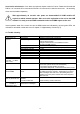
Specifications


28
9. Installations instructions
During in car installation follow this Installation manual instructions as well as
instructions given by car manufacturer concerning installation, operation and usage of
mobile phone or GSM module in the car.
CommandCall control unit install beneath dashboard of the vehicle as low as possible (regarding extreme
high temperatures in summer). Fix the control unit properly with connectors pointing down (to avoid on
wires condensed water to leak in the control unit)
Small rod GSM antenna (included in the kit) or external GSM antenna (on glass stick on type with higher
signal gain, optional accessory) must be connected to CommandCall control unit.
The external GSM antenna is mounted from interior on the windshield or rear car window. Clean and dry
the place where the antenna will be stick on first, tear off protection film from the antenna and stick on the
antenna firmly. Install antenna cable to control unit and screw the connector to SMA connector on the
control unit.
For the cars with metallized glass windows consider using GSM external roof type antenna.
GSM signal level always depends on local conditions and GSM network coverage.
Take care when installing SIM card in the control unit as the card holder is tiny
mechanical part and can be damaged or broken when manipulated wrong way.
Before inserting SIM card into control unit of CommandCall CC2 be sure to check:
• PIN code on SIM card is the same as PIN code written to control unit by PC Setup (it is not important in
the case using of PIN code is disabled on SIM card)
• SIM card has no active divert of phone calls or SMS
• SIM card has no active „Call waiting“ function
Controls installation
ON/OFF push button install in the working area of the driver in place, where is no risk of unwanted
operation for example by the drivers or passenger knee. Drill 10 mm hole for installation (maximal wall
thickness is 2,5 mm). Insert the cable through the hole, lead it to the control unit and connect contact PINs
in respective connector according to wiring diagram.
Temperature sensor T1 install in proper place (in the level of drivers face) for example onto front chassis
column. Lead temperature sensor cable lead to the control unit and connect contact PINs in respective
connector according to wiring diagram. Temperature sensor is used for in car temperature measurement.
Wire harness for connecting independent heater has 7 wires (permanent power supply, heater and
ventilation control signals, external clock signals) terminated with contacts. Wires with terminals insert in
included 4 PIN connector bodies according to wiring diagram. Use corresponding wires from the heater
(refer to wiring diagram supplied with the heater). All remaining wires must be isolated separately.