® CommandCall CC2 GSM communication module User & Installations Manual ESPAR Order # PC Setup 2.2 Control SW 3.
1
Contents 1. Items supplied .................................................... 3 1.1. GSM communications module CommandCall CC2 .................................................... 3 1.2. Accessories .................................................... 4 2. General description .................................................... 5 3. Unit control .................................................... 6 .................................................... 6 3.1.1.
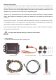
Structure of this manual This manual describes step by step functions of GSM communications module CommandCall CC2, the format of SMS control commands and reports sent to the user, unit controls via phone call with tone dial functions, control via in the vehicle installed ON/OFF push button and gives mounting instructions for unit installation in the vehicle and its connection with the independent heater.
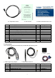
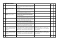
10. Temperature sensor Item 1 2 3 4 5 6 7 8 9 10 11 12 11. User manual Item description CommandCall CC2- full set Control unit Heater wire harness Connector body Tyco 4P (terminals) Connector body Tyco 4P (receptacles) Terminal receptacle (Junior-Power-Timer) Terminals (Junior-Power-Timer) Accessories wire harness ON/OFF push button with LED indication GSM antenna Temperature sensor User & installation manual Basic commands memo card 12.
2. General description GSM communication module CommandCall CC2 is used for transfer of control commands and reports between the user and the vehicle via SMS of GSM network and via phone calls with tone dial function to control connected device via control signals 300 mA.
3. Unit control The user communicates with in the car installed unit via sending and receiving SMS, by making phone call with tone dial function or directly by ON/OFF push button in the vehicle. All mentioned ways of control is possible to combine. Control signals of external clock can be override by SMS commands, by phone call commands or by ON/OFF push button operation. It means if heater was switched ON by external clock then SMS command “0” or pressing ON/OFF push button will switch OFF the heater.
Every type of SMS report has its own checkbox. If respective checkbox is activated then relevant SMS will be sent to the user. If respective checkbox is not activated then relevant SMS is not sent to the user even in the case all other conditions neccessary for its sending are present. By setting checkboxes No.20 to 23 user can select whether information on remaining heating time, actual in car temperature and car battery voltage will be added to relevant SMS reports.
Field 7: actual voltage of vehicle battery in format „vv.v V“ (vv.v is car battery voltage value) In Status SMS containing SMS No.4, 5, 7 - 9, 11 - 13 fields No.1, 5, 6 and 7 must be always present regardless respective checkboxes setting. In Status SMS containing SMS No.6, 10 or 41 fields 1, 6 and 7 must be always present regardless respective checkboxes setting. Individual fields of the Status SMS are separated by comma and next field starts on new line.
3.1.3. SMS control commands Code Check box SMS 1 1 Switch ON the heater for preset time SMS command in form xxxx001 (xxxx is user password) Heater ON by SMS, MMM min., ± ttt.tC, vv.vV will switch ON the heater for preset time and SMS No.4 in range 1 to 120 minutes or unlimitted is sent. When preset time expires system will switch OFF the heater. 4 4 If preset heating time HTTP=999 then heater is switch Heater ON unlimitted, ± ttt.tC, vv.vV ON for unlimitted time and SMS No.12 is sent.
Code Description Text of SMS report Check box 120 Switch ON the heater/ventilation for 120 minutes SMS command in form xxxx120 (xxxx is user password) will switch ON the heater or ventilation, sends SMS No. 4 or 8 (depending on last used status heating/ventilation). 120 minutes later system will switch heater/ventilation OFF. Heater ON by SMS, 120 min., ± ttt.tC, vv.vV or Ventilation ON by SMS, 120 min., ± ttt.tC, vv.vV. NOTE: remaining time must be shown regardless checkbox 30 setting.
Code Command Description Text of SMS report 581 Setting all "triple" checkboxes SMS command in form xxxx581-T1=PPP,T2=PPP, ...,T12=PPP (xxxx is user password) will set all checkboxes as specified by respective P. Each P represent position of stored golden phone number (accepted values 0 to 6). 581 OK 680 Request on actual values of all parameters SMS command in form xxxx680 (xxxx is user password) 680-HTP=mmm,AP=s.s,APH=sss,CBV=vv.
3.2. Switching ON the heater by phone call ringing This function is available only for calls made from phone numbers listed among VIP phone numbers and when checkbox No.25 - “Enable heater/ventilation ON by phone call ringing” is activated. Incoming phone call will be handled as follows: a. phone call is possible to cancel by user within 10 seconds from it start (before the third ring) and in such case nothing happens.
Pressing any other button than 0, 1 to 5 system evaluates as invalid command and requests to input command again. If user inputs 3 times invalid command in the sequence then phone call is terminated. In the case checkbox No.24 is activated and during phone call was given command „3“ then immediately after phone call termination Status SMS will be sent to the user (caller phone). Communication (playing voice messages) can be selected in one from 14 languages.
3.5. Heater control by external clock When checkbox No.27 is activated then signals of external clock will be accepted, when is deactivated then signals of external clock will be ignored by the system. Device will be switched ON by external clock signal in actual mode heater/ventilation and stays ON according to external clock settings. If checkbox No.6 (9) is activated then after switching ON by external clock SMS No.6 - Heater ON by clock, ±ttt.t C, vv.v V or SMS No.9 - Ventilation ON by clock, ±ttt.
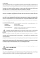
For alarm trigger signal it is possible to set 2 parameters: • AP - minimal signal pulse length which will be accepted by system • APH - time intervall in which system holds alarm signal ON after receiving valid alarm trigger pulse Note to APH setting - APH value should be set long enough to cover the whole alarm cycle, if shorter, then message Alarm trigger may be sent to user several times. Alarm triggers handling, checkbox No.
Logicaly tight handling of car alarmu and ext.device alarm, checkboxes No.28, 29 and 30 are activated APH AP AP AP AP AP car alarm trigger ext.device trigger SMS + call Alarm trigger SMS + call Ext.device trigger no activity SMS + call (pulse< AP) Ext.device trigger no activity (car alarm is not triggered) In the case checkbox No.28 is deactivated SMS report „External device trigger“ will be sent to user every time valid signal of Ext.
keeps system operation for limitted period of time after disconnecting vehicle battery to enable sending emergency reports to the user. After disconnecting power supply it is possible to disconnect backup battery immediately, press and keep pressed ON/OFF push button for 20 seconds. LED will flash twice after elapsing 20 second time and then release push button. 5.3.
5.4. Thermostat - automatic temperature control within preset temperature intervall CommandCall offers automatic temperature control within preset temperature intervall in the case device is switched ON (device switched ON by any method in heating or ventilation mode). By activating checkbox No.18 thermostat function is enabled. Tempreature intervall limits UST1 and UST2 must be set as well as TS1 value.
possibility to recognize that something wrong happened to CommandCall if he/she does not receive SMS report in expected time. It can be caused by system malfunction or just by missing credit for sending SMS reports. For activating this feature tripple checkbox No.33 must contain reference to at least one VIP phone number and desired time interval for sending SMS report must be set by combination of 3 values - number of days, hours and minutes.
6. CommandCall PC Setup Before using CommandCall PC Setup it is necessary to install CommandCall PC Setup programme on your PC. Installation procedure of CommandCall PC Setup programme is described in details in the Chapter 12. Before programming CommandCall the control unit must be switched OFF from the power and backup battery must by cut OFF too (see 3.4.). When backup battery is switched OFF red LED will switch OFF.
Select window of PC Setup for COM port and language selection: After selecting assigned COM port initialization screen of CommandCall PC Setup will be showed for a while: followed by opening of main window of the CommandCall PC Setup: 21
Next are shown parts of PC Setup screens with description of their purpose and the way how to use them: Unit information Version: shows actual version of program stored in CommandCall control unit SIM PIN: insert PIN code of the SIM card which is used in CommandCall 22
6.1. Password settings This part is used for change of password and for enabling/disabling usage of the user password. returns user password value back to factory preset value 1234. Default does not change Default: PIN code of the SIM card inserted into CommandCall control unit.
Part of PC Setup screen for setting single check boxes and their respective SMS report: Part of PC Setup screen for setting tripple check boxes and their respective SMS report: For example shown setting of checkbox No.29 (T1) means that Alarm trigger message will be sent to the sixth VIP number, then to the first VIP phone number and then to the third VIP phone number. Shown setting of checkbox No.33 (T5) means that Periodical connectivity test report will not be sent at all.
6.4. Variables values setting and allowed range Heater preset time HTP: 1 to 120 minutes; whole positive numbers only; 999 = switch ON unlimited Alarm signal pulse length, alarm status hold ON : AP: 0.1 to 9.9 seconds APH: 1 to 999 seconds; whole positive numbers only Car battery voltage, time constant for voltage change stability: CBV: 5.0 to 40.
Initialize: loads factory default values to PC Setup screen and to CommandCall control unit memory Save ... : writes PC Setup screen actual values into file stored in your PC (system will request user to specify file name and location). By this means it is possible to have stored several standard configurations of parameters and SMS texts or archives of specific installations / customer settings stored during unit installation. Load ...
8. USB to COM port converter In the case your computer does not recognize inserted USB Programming Adapter it is necessary to install USB to COM port converter utility (USB to UART conversion). USB to COM port converter utility installation procedure is described in Chapter 13 of this manual. Check if your computer recognised inserted USB Programming Adapter: a.
9. Installations instructions During in car installation follow this Installation manual instructions as well as instructions given by car manufacturer concerning installation, operation and usage of mobile phone or GSM module in the car. CommandCall control unit install beneath dashboard of the vehicle as low as possible (regarding extreme high temperatures in summer).
Accessories wire harness of car alarm and optional outputs consist of 6 wires. Please be informed that PIN No.1 of connector K2 is connected to PIN No.2 of connector K1 inside the control unit. All remaining wires must be isolated separately. Wait approximately 30 seconds after power on CommandCall till GSM module will register to mobile network operator. After successful registration of the unit to the GSM network it is ready to receive SMS commands and to send SMS reports to the user.
11. Wiring diagram 11.1.
11.2.
12. SW Installations 12.1. USB to COM port conversion Connection of your PC with CommandCall control unit for modification and setting parameters and sent SMS contents (texts) is realised via USB port connection. It is serial communication and it is necessary your PC will „recognize“ inserted CommandCall USB Programming Adapter as serial port. This is executed by operation system functions (Win9x/NT/2000/XP) or by using specific driver (program CP210x_VCP_Win2K_XP_S2K3.exe).
d. run CP210x_VCP_Win2K_XP_S2K3.exe program from included Installation CD and accept licence agreement: e. accept the location where Windows drivers will be installed and start of the installation: f.
g. accept final Installation step of the CP210x_VCP_Win2K_XP_S2K3.exe program: h. run „Device Manager“ on your PC to check results of USB to COM port converter installations and check designated COM port number: Note: in used example you can see, that on respective computer COM9 is designated to USB Programming Adapter.
In the case your PC will recognize CommandCall USB Programming Adapter even without Installation of program CP210x_VCP_Win2K_XP_S2K3.exe it is possible the text in name of relevant COM port will be different, but it should be indicated that the port is allocated for USB to COM port converter. In the case COM port designated for USB to UART converter has the number higher than COM9 (for example.
12.2. CommandCall PC Setup Installation Run Setup.exe which is included on Installation CD ROM together with other SW tools of CommandCall GSM communication module. Confirm the start of installation by pressing „OK“: During the Installation follow instructions of installer program: Press the „Next“ button on Welcome screen of CommandCall PC Setup installer program to proceed to Installation folder input.
After accepting or specifying location where the program will be installed press „Next“ again to proceed. Press „Close“ to finish CommandCall PC Setup installation (including all necessary installation components). After installation is completed the program CommandCall PC Setup is ready to use. Part of CommandCall PC Setup installation is the programme .NET Framework 2.1. (in the case it was not installed during Windows installation. Programme .
13.
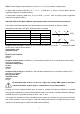
This product conforms with the type approved by Ministry of Transport, Post and Telecommunication of the Slovak Republic on September 28, 2007 under Approval No. E27*10R-02*1199*00 and EC type-approval No. e27*72/245*2006/96*1011*00. For this product following marks were alloted: Copyright © 2009, MOLPIR s.r.o. All rights reserved - it is prohibited to copy, reprint or to circulate any part of this Manual without prior written consent of the author.