
Datasheet


Hand Crimp Tool For 3.96MM (.156”) Pitch KK Crimp Terminals
Doc No: 6382803HM Release Date: 02-27-18 UNCONTROLLED COPY Page 2 of 7
Revision: A Revision Date: 02-27-18
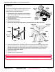
▲Insulation Crimp Note
Due to the terminal’s insulation grip design and/or insulation
diameter range, this tool uses the overlap form geometry in the
insulation punch. This produces an overlap insulation crimp
(A620-compliant). Although the insulation punch profile may
appear lopsided, this is a normal condition for this tool. See figure
to the right. (Some tools with multiple crimp pockets may not
have the overlap profile on all pockets.)
CRIMP SPECIFICATIONS
Terminal Series No.
Bell Mouth
Conductor Brush
mm
In.
mm
In.
8818
0.20-0.50
.008-.020
0.15-0.70
.006-.028
Terminal Series No.
Bend Up
Bend Down
Twist
Roll
Seam
Degree Max.
Degree Max.
8818
3
3
4
8
Seam shall not be
open and no wire allowed
out of the crimping area
After crimping, the crimp profiles should measure the following:
Terminal
Series No.
Wire
Conductor Crimp
Insulation Crimp
Pull Force
Minimum
♦♦ Profile
Height
Width
Height (Ref.)
Width (Ref.)
Wire Type
AWG
mm
In.
mm
In.
mm
In.
mm
In.
N
Lb.
A
B
C
8818
UL1007
18
1.09-1.14
.043-.045
1.85-1.95
.073-.077
2.53
.099
2.54
.100
110
24.7
X
20
1.02-1.09
.040-.043
2.29
.090
2.43
.096
66
14.8
X
22
0.96-1.02
.038-.040
2.14
.084
2.42
.095
53
11.9
X
UL1015
18
1.09-1.14
.043-.045
1.85-1.95
.073-.077
2.69
.106
2.66
.105
110
24.7
X
20
1.02-1.09
.040-.043
2.44
.096
2.49
.098
66
14.8
X
22
0.96-1.02
.038-.040
2.28
.090
2.48
.098
53
11.9
X
♦♦ To achieve IPC-A-620 Class 2 crimps, the following overall wire insulation diameter ranges are recommended:
Profile A: 1.80-2.05mm
Profile B: 1.80-2.00mm
Profile C: 1.75-1.85mm
Tool Qualification Notes
1. (Ref) means the dimension provided is approximate due to the wide range of wires, conductor stranding,
insulation diameter and insulation hardness.
2. An occasional pull force test should be performed. It must exceed the minimum pull force specification.
3. Pull force should be measured with no influence from the insulation crimp. To ensure this, strip the wire long
enough so the terminal insulation grips do not contact the wire insulation.
OVERLAP FORM
GEOMETRY
PUNCH
OVERLAP INSULATION
CRIMP
WIRE
ANVIL