
User Manual


Quality Crimp Handbook
Order No: ATS-638000029 Release Date: 09-04-03 UNCONTROLLED COPY Page 15 of 23
Revision: C Revision Date: 09-12-06
Production
Before the tool is ready for production, the level of capability
needs to be established. Many harness manufacturers run only a
few hundred or few thousand wires at one time. In this case, it is
not practical or economical to run a twenty-five-piece capability
with every set-up.
Visual Inspection
It needs to be standard operating procedure for the operator to
manually fan each bundle of crimped wires and visually check
bell mouth, conductor brush, insulation position, cut-off tab
length, and insulation crimp.
Control Charting
Crimp height is typically control charted because it is a quick
nondestructive measurement and is critical for the termination’s
electrical and mechanical reliability. There are three primary
purposes for control charting. One, the number of setup samples
is usually small, with limited statistical value. Two, since special
cause effects on a process are irregular and unpredictable; it is
necessary to be able to catch changes in the process as soon as
they occur. This prevents thousands of terminations from being
scrapped after the run is over. Three, and most important, this
data is necessary to assess and improve the crimp process.
Once the tooling process is setup and the wire size does not
change, keep one control chart for wire color changes, wire length
changes, terminal material changes, or setup adjustments.
Record the data point on the chart before making a crimp height
adjustment. If data is recorded after each adjustment, the process
is likely to assume control and provide little data for improving
the process. The operator needs to make as many notes as
possible on the chart. The only truly effective and economically
sensible way to manage a manufacturing process is to
understand, monitor and reduce sources of variability that are
inherent to the process itself. Every minute required for setup or
adjustments is unproductive.
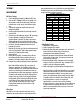
What does this sample chart tell us?
X and R Chart
Control limit for sample of 5 = Avg
(Avg of 5readings) + .577 x Avg (Ranges)
It indicates that a process shift occurred between measurement 12
and 13. This type of shift could occur due to a change in wire, a
change in terminal lots, a jam in the machine that damaged the
tooling, a change in operators, or an adjustment to the insulation
crimp. Since the measurements are still within specification,
would you stop production to adjust crimp height?
A shift in the process due to a change in material may warrant a
crimp height adjustment. A shift after a jam would not indicate
an adjustment, but a close evaluation of the tooling. A shift in the
process between operators would not indicate an adjustment, but
an evaluation of measurement capability. The purpose of a
control chart is to identify what caused the shift in process to
determine if an adjustment to the process is needed.