
Datasheet


Hand Crimp Tool for SL Crimp Terminals
Doc No. ATS-638118700 Release Date: 07-30-07 UNCONTROLLED COPY Page 4 of 8
Revision: E Revision Date: 11-09-17
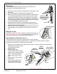
Figure 5
TERMINAL
WIRE
AGAINST THE
WIRE STOP
WIRE
WIRE STOP IS PART OF
THE LOCATOR
PRE
-
STRIPPED
WIRE
TERMINAL
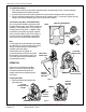
2. Make sure the center of the locator is in the down position. With the
locator attached, push the locator button on the back of the hand tool
to bring the locator forward through the tooling. See Figure 2.
3. While holding the locator button in, load the terminal into the proper
nest opening in the locator based on the wire gauge or terminal type
markings on the hand tooling. See Figure 3.
4. Release the locator button, allowing the locator to return to the
crimping position.
5. Close the tool handle until the first ratchet position engages. See
Figure 4.
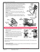
6. Insert the properly stripped wire through the terminal and against the
wire stop. See Figure 5.
7. Crimp the terminal by squeezing the tool handles until the ratchet
mechanism cycle has been completed. Release the handles to open
the jaws.
Note: The tamper-proof ratchet action will not release the tool until it has been fully closed.
8. Remove the crimped terminal from the terminal locator by
pulling on the wire.
9. Visually inspect the crimped terminal for proper crimp
location.
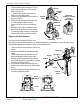
10. On some large OD wires, it may not be possible to insert the
wire with the tool partially closed. Those wires should be
inserted with the hand tool in the open position. Insert the
wire above the terminal in the punch and against the wire
stop, and then close the tool. See Figure 6.
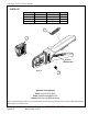
Locator Replacement
See the parts list on the last page of this document for the proper locator order number. Follow the steps below to
replace the locator:
1. Open the crimp hand tool.
2. Squeeze gently on the lower area shown in Figure 7A with your thumb and index finger. The lower tabs of the
locator should disengage from the hand tool.
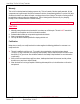
PARTIALLY
CLOSE HANDLE
TOOLING
PARTIALLY
CLOSED
Figure 4
FIRST RATCHET
POSITION
OPEN
POSITION
TERMINAL
Figure 6
WIRE
WIRE
STOP