
Datasheet


Hand Crimp Tool for SL Crimp Terminals
Doc No. ATS-638118700 Release Date: 07-30-07 UNCONTROLLED COPY Page 3 of 8
Revision: E Revision Date: 11-09-17
RELEASE
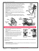
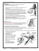
LOCATOR
BUTTON
TERMINAL
Figure 3
LOCATOR
PUSHED THROUGH
TOOLING
TERMINAL
LOCATOR
BUTTON
PUSHED IN
Tool Qualification Notes
1. (Ref) means the dimension provided is approximate due to the wide range of wires, conductor stranding,
insulation diameter and insulation hardness.
2. An occasional pull force test should be performed. It must exceed the minimum pull force specification.
3. Pull force should be measured with no influence from the insulation crimp. To ensure this, strip the wire long
enough so the terminal insulation grips do not contact the wire insulation.
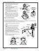
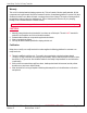
▲Insulation Crimp Note: (32-36 AWG Profile)
Due to the terminal’s insulation grip design and/or
insulation diameter range, this tool uses overlap form
geometry in the insulation punch. This produces an
overlap insulation crimp (A620 – compliant). While
the insulation punch profile may appear “lopsided”,
this is a normal condition for this tool. See figure to
the right. (Some tools with multiple crimp pockets
may not have the “overlap” profile on all pockets).
Note
A crimp height chart is provided with this document
as a reference only. Due to the wide range of wires,
strands, insulation diameters and durometers
available, actual crimp height
measurements may very slightly. An
occasional destructive pull force test should
be performed to check hand tool crimp. Pull
Force value must exceed the minimum pull
force specifications listed.
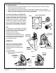
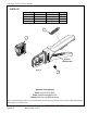
OPERATION
Open the tool by squeezing the handles
together. At the end of the closing stroke,
the ratchet mechanism will release the
handles and the hand tool will spring open.
See Figure 1.
Crimping Terminals
1. Select the desired terminal listed in the
preceding charts.
SQUEEZE
HANDLES
TOGETHER
HANDLE WILL
SPRING OPEN
Figure 1
LOCATOR IN
DOWN POSTION
PUSH ON THE
LOCATOR BUTTON
Figure 2
OVERLAP
INSULATION
CRIMP
OVERLAP FORM GEOMETRY
ANVIL
PUNCH
WIRE