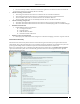
Administration Tab Creating a Configuration Template for an Authorized SSID Create SSID Template allows you to specify the details for creating a new SSID as follows: Authorized SSID: Displays the name of the SSID that you have added earlier This is a Guest SSID: Select this option if this SSID is a Guest SSID used to provide Wi-Fi connectivity to visitors and guests. Though APs with Guest SSID are Authorized, they may be treated differently than APs that are used by employees for corporate access.
Administration Tab Description: Write a short description to help identify the SSID template Network Protocol allows you to select the allowed 802.11 protocols for the SSID: Any: Allow APs with any network protocol for this SSID Select: Specify the 802.11 protocol on which the system allows the APs connected to the network to operate–802.11 a, 802.11 b/g, and 802.11b only AP Capabilities allows you to select the additional capabilities that Authorized APs may have.
Administration Tab A policy is collection of SSID templates attached to that location. You can apply an SSID template from the parent or create it locally; if you wish to customize the WLAN policy for that location. Other templates may be available to be attached but are not part of the WLAN policy and will not be used for AP classification. The SSID Templates section lists the SSID templates that are available at a particular location.
Administration Tab Determining Policy Compliance Select No Wi-Fi Networks This section allows you to specify the list of networks at the selected location where no Wi-Fi APs are allowed to be connected. The No Wi-Fi Networks list at a location takes precedence over the list of networks in SSID templates applied at that location.
Administration Tab No Wi-Fi Network Networks Monitored by the System: Specifies the networks monitored by the system. No Wi-Fi Networks at this Location: Specifies the networks to which no Wi-Fi AP should be connected at the selected location. You can move a network from Networks Monitored by the System to No Wi-Fi Networks at this Location. Click Add to enter a new network address to add a No Wi-Fi network at the selected location.
Administration Tab RSSI based Classification Operating Policies Select the Operating Policies screen to set the operating policies in the system. You can set the location-wise AP autoclassification policy, client auto-classification policy, intrusion prevention levels and policy. AP auto-classification The AP Auto-Classification policy function enables you to specify the AP classification policy for different AP categories.
Administration Tab AP Auto-Classification Policy Under External APs, AirTight recommends that you select Automatically move Potentially External APs in the Uncategorized list to the External Folder. The system automatically removes an AP from the External folder and moves it to an appropriate AP folder if it later detects that the AP is wired to the enterprise network.
Administration Tab Client Auto-Classification Policy Under Initial Client Classification, specify if newly discovered Clients at a particular location, which are Uncategorized by default should be classified as External, Authorized or Guest. Under Automatic Client Classification, select one or more options to enable the system automatically re-classify Uncategorized and Unauthorized Clients based on their associations with APs. You can categorize the following types of Clients.
Administration Tab Do not re-classify a Client as Guest if its wireless data packets are not detected on the wired network (except if the connection is reported by WLAN controller) Clients connecting to External APs All Uncategorized Clients that connect to an External AP are reclassified as External All Uncategorized Clients that connect to a Potentially External AP are classified as External All Guest Clients that connect to an External AP are re-classified as External All Guest Cli
Administration Tab Intrusion Prevention Policy You can enable intrusion prevention against the following threats: Rogue APs: APs connected to your network but not authorized by the administrator; an attacker can gain access to your network through the Rogue APs. You can also automatically quarantine Uncategorized Indeterminate and Banned APs connected to the network.
Administration Tab Special Handling for Smart Devices Non-authorized Associations: Non-authorized and Banned Clients that connect to Authorized APs; an attacker can gain access to your network through Authorized APs if the security mechanisms are weak. Non-authorized or Uncategorized Client connections to an Authorized AP using a Guest SSID are not treated as unauthorized associations.
Administration Tab Intrusion Prevention Level You can select the following prevention levels: Block: A single sensor can block unwanted communication on any one channel in the 802.11b/g band and any one channel in the 802.11a band. Disrupt: A single sensor can disrupt unwanted communication on any two channels in the 802.11b/g band and any two channels in the 802.11a band. Interrupt: A single sensor can interrupt unwanted communication on any three channels in the 802.
Administration Tab Event Configuration comprises of the following main tabs: Security System Performance Security Security enables you to view events that indicate security vulnerability or breach in your network. Security events are further divided into the following sub-categories: Rogue AP Mis-Configured AP Misbehaving Clients Prevention DOS Ad hoc Network Man-in-the-Middle MAC Spoofing Reconnaissance Cracking Note: Prevention tab is not available with WIDS.
Administration Tab Event Configuration The events list displays the following columns: Activity Status Icon: Specifies the activity status of the event – Live or Instantaneous. Display: Select the checkboxes that correspond to the types of events that you want to appear in the main Events screen.
Administration Tab Event Advanced Settings Email Notification The Email Notification screen enables you to select the email addresses that should be notified when an event occurs at a particular location. You can select from the email addresses of system users or add a new email address.
Administration Tab Email Notification Click Add to open Custom Email Address for Notification dialog where you can add a new email address. Custom Email Addresses for Notification Dialog Click OK to add the new email address. Select an email address and click Delete to delete an existing email address. You can delete multiple email addresses using click-and-drag or using the + keys and then clicking Delete.
Administration Tab SSID Profile Configure SSID Profiles using the SSID Profile. SSID Profile To add a wireless SSID profile, click Add New Profile. You can add multiple SSID profiles for the Sensor/AP combo operating in the AP mode. When in AP mode, a single physical AP device can be logically split up into multiple virtual AP's. Each wireless profile represents the configuration settings of a virtual AP. Multiple virtual APs can be configured on a single radio.
Administration Tab WPA: WPA stands for Wi-Fi Protected Access. It is the security protocol that eliminates the shortcomings of WEP. WPA2: WPA2 is the latest and more robust security protocol. It fully implements the IEEE 802.11i standard. WPA and WPA2 mixed mode: This stands for a mix of the WPA and WPA2 protocols. PSK or Personal Shared key is generally used for small office networks. In case of bigger enterprise networks, RADIUS authentication is used.
Administration Tab Basic Settings The following table explains the fields present on the Basic Settings tab. Field Profile Name Description Default value This field specifies the name of the profile.
Administration Tab SSID This field specifies the SSID of the wireless profile. This is a mandatory field. Broadcast SSID This check box indicates whether the SSID is to be broadcast The check box is selected, or not for this Virtual AP, in the beacon frames. If selected, the indicating that the SSID beacon for this Virtual AP carries the SSID. is broadcast. Client Isolation This check box indicates whether communication between 2 wireless clients of this virtual AP is enabled or disabled.
Administration Tab PSK Select the PSK option if you want to use a personal shared key. The Pass phrase field is enabled when this option is selected. PSK Pass Phrase Specify the shared key of length 8-63 ASCII characters for PSK authentication blank Show Key Select this check box to see the actual pass phrase on the screen. If this check box is cleared, the key is masked. clear 802.1x Select 802.1x option if you want to use a RADIUS server for authentication.
Administration Tab Server IP Enter the IP Address of the primary accounting server here. blank Port Number Enter the port number at which primary accounting server listens for client requests. 1813 Shared Secret Enter the secret shared between the primary accounting server and the AP. blank Show Select this check box to see the actual text of the shared secret on the screen. If this check box is cleared, the key is masked.
Administration Tab Network Settings Configure the VLAN and DHCP settings to be used be the NAT device using the Network Settings tab. VLAN ID: Specify the VLAN ID. Start IP address: Specify the starting IP address of the DHCP address pool in the selected network ID. End IP address: Specify the end IP address of the DHCP address pool in the selected network ID. Local IP address: Specify an IP address in selected network ID outside of the DHCP address pool.
Administration Tab Guest clients will be allowed to make DNS queries to specific servers only. Specify at least one DNS server by clicking Add.. under DNS Servers. The following screen appears on clicking Add.. Add DNS Server You can specify up to three DNS server IP addresses. Requests to a DNS server, not specified under DNS Servers, are dropped. Guest users cannot configure DNS servers of their choice.
Administration Tab Guest Portal A guest network is used to provide restricted wireless connectivity (e.g., Internet only) to guests. Currently ONLY one wireless profile can be configured as a guest network. Select Enable Splash Page to enable the splash page display. The portal consists of a web page with a submit button. The portal supports only ‘click-through’; authentication is not supported.
Administration Tab The zip file should have a file with the name “index.html” at the root level (i.e., outside of any other folder). This is the main portal page. It can have other files and folders, (and folder within folders) at the root level that are referenced by the index.html file. The total unzipped size of the files in the bundle should be less than 100 KB.
Administration Tab Specify the Redirect URL. The browser is redirected to this URL after the user clicks the submit button on the portal page. If left empty, the browser is redirected to the original URL accessed from the browser for which the portal page was displayed. Walled Garden Settings: Configure a list of exempted IP address ranges. (E.g. 192.168.1.0/24) . HTTP and HTTPS services on these IP addresses can be accessed without redirection to the portal page. If some part of the portal page (e.g.
Administration Tab Firewall Settings To enable firewall, select Enable Firewall. Click Append New Rule to add the first rule or a new rule at the end of the existing rules. If you want to add a new rule between 2 rules, click Add New Rule between the 2 rules. Specify the name of the rule in Rule Name, and the host name or IP address to which the rule applies in IP Address/Host Name. Specify the port number in Port. Specify the action Allow or Block. Specify the Protocol in Protocol.
Administration Tab Define the default rule by selecting Allow or Block to allow or block any type of requests from IP addresses or host names for which rules have not been defined. Click Delete in the rule to delete the rule. Traffic Shaping & QOS The values of the QoS parameters will depend on the type of applications that are used over the network. You can specify the QoS parameters using the Traffic Shaping & QOS tab.
Administration Tab You can restrict the upload and download traffic on the SSID to a specific limit. Select Restrict upload traffic on this SSID to and enter a value to restrict the upload traffic for the SSID. Select Restrict download traffic on this SSID to and enter a value to restrict the download traffic for the SSID. If you configure the radio in 11N mode, WMM (Wi-Fi multimedia) will always be enabled, irrespective of whether or not you select the WMM check box, in the SSID profile.
Administration Tab BYOD - Device Onboarding Select the Enable Device Onboarding check box to enable this technique. Select Smart Clients Only if you want this technique to be enabled for unapproved smart client but not for other wireless clients (like laptops etc.) Select All Clients if you want to enable this technique for all types of unapproved wireless clients. Specify the URL of the splash page in Redirect to URL. Wireless clients will be redirected to this URL upon making any web request.
Administration Tab The IP address or hostname of the splash page host must be added to the walled garden settings for the redirection to work. Any other hostname or IP address that needs to be exempted from redirection can also be added here. Use Add and Delete to modify the list of exempted hostnames or IP addresses. Device Template You can create different templates to be applied to AirTight devices through this screen.
Administration Tab Note: The system stores the default device configuration in a predefined template System Template. You cannot delete the System Template nor edit its name; it is unique. When a device is added or discovered, it is automatically assigned the configuration settings in this template. You are allowed to edit the configuration settings in the System Template to effect default configuration of your choice.
Administration Tab When you select operation mode as Access Point, the other fields on the SS-300-AT-C-60 tab get enabled. In case the operation mode is WIPS sensor, these fields remain disabled. SS-300-AT-C-60 has 2 radios. You can separately configure the 2 radios, Radio 1 and Radio 2. You can add multiple SSID profiles to be monitored by the SS-300-AT-C-60 devices operating in AP mode. The following table describes the fields related to Radio Settings.
Administration Tab Frame Aggregation This field specifies the enabling or disabling of MPDU aggregation This field is 802.11n specific. When in AP mode, a single physical AP device can be logically split up into multiple virtual AP's. Each wireless profile represents the configuration settings of a virtual AP. Click Add New Profile to select the SSID profiles for the AP. Each SSID profile corresponds to a virtual AP. Upto 8 virtual APs can be configured on one radio.
Administration Tab Channel Frequency Table Channels to Monitor: Specifies the 802.11a and b/g channels to be used by sensors to monitor WLAN traffic. Select the check box Select All Standard Channels to select a superset of all the channels. For 802.11a, the standard sets of channels are 184 – 216 and 34 - 165. By default, this check box is selected. Select the check box Select All Allowed Channels to select all the allowed channels in the selected operating region.
Administration Tab well. If you deselect a channel from Channels to Monitor, then this channel is also deselected from Channels to Defend section. For operating region US, if you select channel 184, 188, 192, or 196 under Channels to Monitor or Channels to Defend, and click Save, the following message box appears. Warning while turning on channel in US safety band If you click Yes, the channel is selected. If you click No, the channel is not selected.
Administration Tab VLAN Settings To add VLANs to be monitored, select the Enable VLAN Monitoring check box. Click Add to add a VLAN. Add VLAN Enter the VLAN ID and click OK, to add the VLAN to the list of monitored VLANs. When you save changes to the VLAN Settings tab by clicking Save, an additional confirmation message appears, after clicking OK on the Confirmation-Save message.
Administration Tab Confirmation-Save VLAN Settings The VLAN Settings are saved only when Yes is clicked on this message. If you click No, the Confirmation-Save message will re-appear. The VLANs created should not exceed the “MAX allowed VLAN to monitor” for the sensor mode. If the number of VLANs specified by user exceeds this maximum count, the maximum VLANs (created &) monitored should be the first maximum VLAN entered by user in sensor template.
Administration Tab Sensor Password Configuration Under Sensor Password Configuration tab specify the following: Current Password state: Specifies that the new password must be the same as the one specified in the System Template. New Password: Enter the new password to be assigned as user ‘config’ password for all sensors associated with the sensor template being edited. Confirm Password: Reenter the password to help confirm the new password before saving.
Administration Tab Offline Sensor Configuration-Offline Sensor Parameters Enable offline Sensor mode: Select this checkbox to enable the offline sensor mode. When the offline sensor mode is enabled, the sensor continues to detect and classify devices, raise event alerts, and prevent ongoing threats.
Administration Tab Offline Sensor Configuration-Device Classification Policy Under Device Classification Policy tab specify the desired classification policies to move APs and Clients from the Uncategorized list to the Categorized list: Under AP Classification Policy, select one or more options to enable the system automatically move APs from the Uncategorized AP list to the Categorized AP list: Move networked APs to the Rogue or Authorized AP folder in the Categorized AP List Move non-networked A
Administration Tab Offline Sensor Configuration-Intrusion Prevention Policy Under Intrusion Prevention Policy tab enable intrusion prevention against the following threats: Rogue APs APs categorized as Rogue Uncategorized APs that are connected to the network Misconfigured APs APs categorized as Authorized but using no security mechanism (Open) APs categorized as Authorized but using weak security mechanism (WEP) Client Mis-associations Authorized Client connections to APs categorized as E
Administration Tab Additionally, specify the intrusion prevention level that allows you to choose a trade-off between the desired level of prevention and the desired number of multiple simultaneous preventions across radio channels. You can choose either of the following prevention levels: Block Disrupt Interrupt Degrade Antenna Selection and Port Assignment Antenna connectivity setting is an advanced setting and should be used with utmost care.
Administration Tab Antenna Selection and Port Assignment Under Antenna Selection and Port Assignment tab 1 For Port Assignment for SS-200 Sensor Select Diversity On or Diversity Off Diversity On: This is the default setting, which means both the antennas are dual band. Select this option if you have a dual band (2.4 GHz and 5 GHz) antenna connected to both the ports on the sensor.
Administration Tab Antenna Selection and Port Assignment-SS-300-AT 2 For Antenna Selection for SS-300-AT Sensor Select Internal or External in Antenna Selection. The default configuration for SS-300-AT sensors is to use internal antennas. If you want to connect external antennas to SS-300-AT sensors, select External radio button. This enables: Antenna Ports Used: Six external antenna ports are available in every SS-300-AT type sensors. Out of these six ports, three ports are for 5 GHz and three for 2.
Administration Tab Points to note for SS-300 Sensor – Antenna Selection 1 Antenna selection feature is not available in SS-300-AT-C-01 model type. For this model, internal antennas will be selected irrespective of the “Antenna Selection” settings. 2 There is no need to perform any special configuration for connecting external antenna for SS-200-AT type of sensors. You can simply connect external antenna for SS-200-AT sensors.
Administration Tab Antenna Ports Used: Three external antenna ports are available in every SS-300-AT-C-50 type sensors. Depending upon number of external antennas connected; click the checkboxes corresponding to the antenna ports in the sensor template. Indentation marks are provided on the sensor enclosure describing the radio and antenna port, like 2.4G/5G Ant 1, 2.4G/5G Ant 2, and 2.4G/5G Ant 3. Note: To derive the full benefit of 802.11n range and to be able to capture all 802.
Administration Tab Antenna Selection and Port Assignment-SS-300-AT-C-60 ii. For Antenna Selection for SS-300-AT-C-60 Select Internal or External in Antenna Selection. The default configuration for SS-300-AT-C-60 is to use internal antennas. Sensor Access Log The System provides you with a provision to send the sensor access logs to the Syslog server. Following logs could be sent to a Syslog server of user's choice: 1.
Administration Tab that particular sensor. The configuration of Syslog server IP to which the sensor access logs are to be sent, is done through the Sensor Access Log tab. The following screen shows the Sensor Access Log tab. Sensor Access Logs The following fields are present in the Sensor Access Logs tab: Enable Sensor Access Logging: Select the Enable Sensor Access Logging check box, to enable sending of sensor access logs to a Syslog server. This checkbox is deselected, by default.
Administration Tab Note: Check the firewall settings of the Syslog server and modify them, if needed, so that the System is able to send the logs to the Syslog server. Location Properties The Location Properties option enables you to define high-level administrative settings for a selected location. These settings take precedence over any conflicting policies.
Administration Tab Note: If you deploy new Authorized APs later, you do not have to deactivate intrusion prevention. However, you need to ensure that the newly deployed APs are moved to the Authorized folder. Intrusion Prevention Activation Device List Locking You can lock the list of Authorized APs and Clients for a selected location by checking the two check boxes Lock AP List for location ‘ and Lock Client List for location ‘.
Administration Tab Device List Locking SpectraGuard® Enterprise User Guide 323
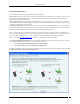
Appendix A1:SNMP Interface Appendix A1:SNMP Interface The system sends traps to an SNMP management station when a Sensor generates an event. You can view a trap sent from the system using SNMP manager software such as HP Open View or MG Soft MIB (Management Information Base) browser. The SNMP manager software allows you to view a detailed description of the trap and thereby the functioning of your wireless network.
Appendix A2:Syslog Interface Appendix A2:Syslog Interface SGE also sends events as Syslog messages. Any standard Syslog receiver (e.g. Syslog watcher from snmpsoft) can be used to monitor the Syslog messages sent by SGE. SGE can send Syslog messages either 'Plain Text' or 'IDMEF' format based on the 'Message Format' selected while configuring Syslog receivers on Syslog configuration screen. The format of 'Plain Text' Syslog message is shown below.
Appendix A2:Syslog Interface " All Syslog messages are sent with Syslog facility as 'System' and Syslog severity as 'Critical', 'Info' or 'Warning' based of SpectraGuard Enterprise event severity.
Appendix B:Glossary of Terms and Icons Glossary of Terms and Icons This section provides a quick reference to wireless networking terms and acronyms used in the guide.
Appendix B:Glossary of Terms and Icons SSL Secure Socket Layer UDP User Datagram Protocol VPN Virtual Private Network WEP Wired Equivalent Privacy WLAN Wireless Local Area Network WLSE Wireless LAN Solution Engine Glossary of Terms Term Description .SPM file Planner File, a proprietary AirTight® Networks file format that holds information about RF signal values, placement of devices, and device settings 802.
Appendix B:Glossary of Terms and Icons Dual Radio AP An AP with two radios to support Clients on multiple bands Hostname A unique name by which a computer is identified on the network Indeterminate AP An AP for which the system cannot determine whether it is plugged into your wired network.
Appendix B:Glossary of Terms and Icons Software AP Software implementation of AP functionalities that permits a WLAN enabled device to act as an AP SSID A unique token identifying an 802.
Appendix B:Glossary of Terms and Icons Refresh: The button with this icon refreshes the current screen. Help: The button with this icon displays the Product Help. Legends: The button with this icon displays the list of icons used on the product screens and their description. About SpectraGuard Enterprise: The button with this icon displays the product version, patent number, and license information of the system. Log Off: The button with this icon allows you to logout from the Console.
Appendix B:Glossary of Terms and Icons Edit Policy: The button with this icon enables you to edit policies. More Information: The button with this icon enables you to view more information in a graphics–text format on a particular section. Bar Chart: This button with this icon enables you to view a bar graph of data. Pie Chart: This button with this icon enables you to view a pie graph of data. Table View: This button with this icon enables you to view the table view of data.
Appendix B:Glossary of Terms and Icons Instantaneous: This icon indicates an instantaneous event that are triggered based on a trigger that do not have continuity. Expired: This icon indicates an expired event in which the triggers that raised the event are not operational or have ceased to exist; this event has a valid start and stop time stamp. Secure: This icon indicates an event that does not contribute to the vulnerability status of the system.
Appendix B:Glossary of Terms and Icons Merged AP-Inactive: This icon shows that a merged AP that was earlier visible to Sensor(s) is inactive. Misconfigured Merged AP-Active: This icon shows that at least one BSSID in an active merged AP is misconfigured Misconfigured Merged AP-Inactive: This icon shows that at least one BSSID in an inactive merged AP is misconfigured. Single AP: This icon shows a radio for an AP. Authorized Merge AP: This icon shows a merged AP (AP with mutliple BSSIDs).
Appendix B:Glossary of Terms and Icons Authorized Client-Active: This icon shows that an Authorized Client is active and visible to Sensor(s). Authorized Client-Inactive: This icon shows that an Authorized Client that was earlier visible to Sensor(s) is inactive. Rogue Client-Active: This icon shows that a Rogue Client is active and visible to Sensor(s). Rogue Client-Inactive: This icon shows that a Rogue Client that was earlier visible to Sensor(s) is inactive.
Appendix B:Glossary of Terms and Icons SAFE Client-With Only Wired Interface: This icon shows a SAFE Client that has only a wired interface. SAFE Report Available: This icon indicates that a SAFE report generated earlier is available for the selected Client. SAFE Report Not Available: This icon indicates that a SAFE report is never generated for the selected Client. SAFE Report Scheduled: This icon indicates that a SAFE report will be generated for the selected Client when it become active.
Appendix B:Glossary of Terms and Icons Sensor Version Mismatch: This icon shows that the Sensor software version is higher than that of the Server. Network Detector-Active: This icon shows that the ND is connected to the Server and is currently contributing into wired detection of APs. Network Detector-Inactive: This icon shows that the ND is not connected to the Server and is currently not contributing into wired detection of APs.
Appendix B:Glossary of Terms and Icons Add Location: The button with this icon allows you to create a new location folder or node. Edit Properties: The button with this icon allows you to edit the properties of the existing location folder or node. Import Location: The button with this icon allows you to import a file in .SPM format for a specific location from a specified path. Delete: The button with this icon allows you to delete selected item/entity.
Appendix B:Glossary of Terms and Icons Icon Name: Description Global Policies: The button with this icon indicates policies that are applicable to all the locations defined in the system. Local Policies: The button with this icon indicates policies that are specific to a particular location defined in the system. Custom Defined Policy: This icon signifies a policy group whose policies are custom defined. Inherited Policy: This icon signifies a policy group whose policies are inherited.