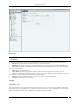
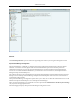
Administration Tab View Logs Recommendation: In order to properly view the multilingual characters, download the log file in .TSV format and view it in Excel. In the log file, different log records are listed in different rows.
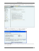
Administration Tab Select the check box, Check for availability of Server upgrade at each login, to enable the system automatically check if an upgrade is available when you log into the console. Upgrade If you have modified the Upgrade Link, to save it click on the Upgrade screen. To check if an upgrade is available for the server, click . If an upgrade is available, an Upgrade Available dialog appears.
Administration Tab Click OK or close the dialog to close the Upgrade Available dialog. Alternatively, click Ignore Upgrade Notification to ignore the upgrade notification until you log out of the Console. If an upgrade is not available, an Upgrade Not Available dialog appears. Click to close the dialog. Upgrade Not Available Dialog Upgrade SpectraGuard Enterprise Now Prerequisites: 1 Sun Java Runtime Environment (JRE) version 1.
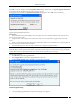
Administration Tab Uploading Upgrade Bundle Progress Bar 5 You can cancel the upgrade by clicking Cancel anytime while the Upgrade Bundle upload is in progress. 6 After the Server Upgrade Bundle upload is complete, Server Upgrade starts automatically. 7 Close the current browser window. A new window, Server Upgrade Progress, is launched which displays the status of the Server Upgrade process. Follow the instructions displayed on the Server Upgrade Progress window.
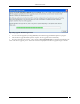
Administration Tab Server Upgrade Progress Window Note: You cannot abort or cancel the Server Upgrade process once the Server Upgrade Progress window is launched. Additionally, the Server Upgrade process continues even if the Server Upgrade Progress window is closed. 8 After the server upgrade is successful, the server reboots automatically. 9 After you have read all instructions on the Server Upgrade Progress window, close all the Web browser windows including the Server Upgrade Progress window.
Administration Tab HA Status HA Status: This is a read-only section and displays the following information: HA Status: Displays the status of the HA Cluster. Standalone: This state indicates that the server is in Standalone mode. Up: This state indicates that the HA Cluster is up and running. Other Server Not Reachable: This state indicates that the Standby server is not reachable over the HA interface link.
Administration Tab Error: This state indicates an error in HA state. Contact Technical Support. Cluster IP Address: This IP Address can be used by the Console and Sensors to connect to the HA cluster. This is a virtual IP Address used to connect to the HA cluster. Cluster IP address is optional. It can not be used in Layer3 HA configuration.
Administration Tab Login Configuration Under Configure Login Message: Select the checkbox, View Login Message to show the login message on the Console login page. Console Login Message: Specifies the login message to display on the Console and on the banner message of SGE CLI screen. The Login screen with the specified Console Login Message appears as follows.
Administration Tab Login Screen with the Console Login Message Under Concurrent Console Login Settings: Concurrent Sessions per User: Configures the maximum number of concurrent console login sessions per user. (Minimum: 1, Maximum: 5, Default: 5) Wizard The system’s Setup Wizard systematically takes you through a recommended sequence of configuration screens that enable you to set up your system completely. This wizard does not remember or apply any configuration changes. It is simply a tour guide.
Administration Tab Wizards Click Start Setup Wizard to open a Confirm message dialog that confirms your navigation through the wizard. SpectraGuard Manager Configuration SpectraGuard Manager establishes a communication channel with SpectraGuard Enterprise through a digital certificate. Version 6.6 onwards, digital certificate-based authentication replaces the username-password authentication required to log in to the SpectraGuard Enterprise Console through the SpectraGuard Manager Console.
Administration Tab SpectraGuard Manager Configuration Adding the digital certificate to SpectraGuard Enterprise Server Before adding the certificate to the SpectraGuard Enterprise server, it must be downloaded from the SpectraGuard Manager console, and saved to the desired location. To add the certificate to the SpectraGuard Enterprise server, click Add on the SpectraGuard Manager Configuration screen.
Administration Tab The system integrates with Aruba Mobility Controllers. It fetches wireless device details and RSSI information from the Aruba Mobility Controllers and thus helps to manage the WLAN infrastructure. The Aruba WLAN architecture consists of Aruba Mobility Controllers and APs. At any time, the Aruba Mobility Controller has all the information about the APs and devices seen/associated with these APs.
Administration Tab 80%. If the utilization exceeds 80%,the system performance may degrade and result in side effects such as sluggish UI and sensor disconnections. Under Automatic Synchronization Settings, select the System-Aruba Mobility Controller synchronization interval.
Administration Tab Note: Configured Aruba Mobility Controllers will use the DNS names and DNS suffixes configured by the user in the Server Initialization and Setup Wizard on the Config Shell. Community String: Specifies the user defined community string using which the system communicates with the Aruba Mobility Controller. (Default: public) Port Number: Specifies the port number of the Aruba Mobility Controller from which data is imported.
Administration Tab Increased scalability Simplified, centralized management Zero-touch AP deployment and configuration Network-wide monitoring Cisco WLC The Cisco Unified WLAN architecture consists of Wireless LAN Controllers (WLC) and APs. The APs are managed using Light Weight Access Point Protocol (LWAPP). At any time, the WLC has all the information about the APs and devices seen/associated with these APs. Integration with Cisco WLC allows the system to fetch this information from WLC.
Administration Tab System server is stopped Internal error, in which case you need to contact Technical Support Imported APs: This percentage indicates total number of APs imported from WLC(s) as a fraction of maximum allowed. The maximum allowed depends on type of appliance. The status displayed is as of the last synchronization event. It is recommended that the utilization remains below 80%.
Administration Tab WLAN Controller Dialog WLAN Controller contains the following fields: Controller (IP Address/Hostname): Specifies the IP address or the hostname of the WLC with which the system communicates. Note: Configured WLCs will use the DNS names and DNS suffixes configured by the user in the Server Initialization and Setup Wizard on the Config Shell. Community String: Specifies the user defined community string using which the system communicates with the WLC.
Administration Tab (Default: Disabled) Import Signal Strength Information?: Indicates if the signal strength of the managed devices is to be imported into the system. (Default: Enabled) Note: Location Tracking results may vary depending on the Channel scan settings set on the WLC. Click to add the details for a new WLC. Click to confirm the validity of IP Address/Hostname, SNMP settings, and version compatibility of the newly added Lwapp Controller.
Administration Tab Cisco WLSE WLSE Integration Status: If WLSE integration is enabled, the system interacts with the configured WLSE server. Else, WLSE integration services are shut off. If you select WLSE Integration Enabled, you can configure the following WLSE Server Settings. The system disables WLSE by default. Current Status: Displays the Current Status of the WLSE server: Running or Stopped.
Administration Tab Note: When you select the option All WLSE-managed APs automatically move to the Authorized AP folder and connect a Rogue AP to the network, the port to which the AP is connected is not blocked. This is a limitation of the WLSE API. In other words, the WLSE API provides only tracing functionality and not shutdown functionality. Automatic Synchronization Settings: Specifies the interval at which the server should automatically synchronize with the WLSE server.
Administration Tab HP MSM Controller The HP MSM Controller manages a collection of thin APs. The HP MSM architecture consists of MSM Controllers and the APs that are managed by these controllers. Integration with HP MSM Controller allows the system to fetch information about Synchronized APs. Using this information, the system automatically classifies these devices. HP MSM Controller Integration Important: The system supports HP MSM Controller version 5.4.2 or higher.
Administration Tab Certificate Store. Click Download to download a pre-generated Client Certificate for the system. Following figure displays the dialog box that appears on clicking the Download button. Client Certificate Download Dialog Click Save to download and save the Client Certificate to the appropriate directory. Upload this Client Certificate into the MSM Controller’s Trusted CA Certificate Store using its management tool. The system is now setup and ready to communicate with the MSM Controller.
Administration Tab Add HP MSM Controller Dialog HP MSM Controller contains the following fields: Controller Name or IP Address: Specifies the Controller Name or IP address of the HP MSM Controller with which the system communicates. Port Number: Specifies the port number of the HP MSM Controller from which data is imported. (Default: 448) Authentication: Secure Http (SSL/TLS): Select this option if the MSM Controller is configured to use HTTPS for authentication.
Administration Tab Select a row and click Disable to disable the selected HP MSM Controller. You can disable multiple HP MSM Controller details using click-and-drag or using the + keys and then clicking Disable. Checking configuration status of an HP MSM Controller Select a MSM Controller row under MSM Controllers and click the Test button. The System will return Pass status if the HP MSM Controller has been correctly configured.
Administration Tab Meru Select Enable Virtual Cell and Virtual Port Support check box to activate support for Meru Virtual Cell and Virtual Port architecture. Click a dialog appears to restart the server to activate the changes. Server restart dialog Click Yes. A confirmation dialog appears that the configuration settings have been saved successfully.
Administration Tab The Enterprise Security Management (ESM) Integration screen allows configuration of various ESM integrations that collect, analyze, and display events. The system integrates with ArcSight’s Enterprise Security Management (ESM) infrastructure by sending events to the designated ArcSight server. The ArcSight server is configured to accept syslog messages having detailed event information in ArcSight’s Common Event Format (CEF).
Administration Tab ArcSight Configuration Dialog ArcSight Configuration dialog contains the following fields: ArcSight Server (IP Address/Hostname): Specifies the IP Address or the hostname of the destination ArcSight server to which the CEF formatted messages are sent. Note: Configured ArcSight servers will use the DNS names and DNS suffixes configured by the user in the Server Initialization and Setup Wizard on the Config Shell.
Administration Tab SNMP SNMP Integration Status: If SNMP integration is enabled, the system sends SNMP traps to the configured SNMP servers. Other systems can do an SNMP Get to this server. Otherwise, SNMP integration services are shut off. If you select SNMP Integration Enabled, you can edit and manage SNMP server details. The system enables SNMP by default. Current Status: Displays the Current Status of the SNMP server: Running or Stopped.
Administration Tab IF MIB Host Resources MIB AirTight-MIB: If selected, the system enables the external SNMP Trap receivers to receive traps MIB-II: If selected, configure the System Contact, System Name, and System Location. (Default System Name: Wi-Fi Security Sever) Note: IF MIB, Host Resources MIB, an MIB II are standard MIBs that you can download from the Internet. For AirTight-MIB, contact AirTight Technical Support.
Administration Tab Editing a SNMP Trap Destination Server Double-click a row or click Edit to open SNMP Configuration dialog similar to the one shown above to update the SNMP server details. Click Save to save all settings. Deleting an SNMP Trap Destination Server Select a row and click Delete to discard the details of an existing SNMP server. Syslog Integrating with Syslog servers The Syslog screen allows the server to send events to designated Syslog receivers.
Administration Tab Under Manage Syslog Severs, click to open Syslog Configuration dialog where you can add Syslog server details. Syslog Configuration Dialog Syslog Configuration contains the following fields: Syslog Server (IP Address/Hostname): Specifies the IP address or the hostname of the Syslog server to which events should be sent.
Administration Tab OPSEC Operations Security (OPSEC) is an analytic process used to deny an adversary information – generally unclassified – concerning our intentions and capabilities by identifying, controlling, and protecting indicators associated with our planning processes or operations. OPSEC does not replace other security disciplines – it supplements them. OPSEC Integration with OPSEC enables the system to send events to the specified OPSEC server.
Administration Tab SSL SSL OPSEC SSL Clear SSL Clear OPSEC FWN Auth OPSEC SSL CA SSL CA Comp SSL CA RC4 SSL CA RC4 Comp Asymmetric SSL CA Asymmetric SSL CA Comp Asymmetric SSL CA RC4 Asymmetric SSL CA RC4 Comp SSLA Clear Under SIC Settings, you need to specify the following settings for the Simple Instructional Computer (SIC) for all the authentication types except ‘Clear’: Server SIC Name: Specifies the server name of the SIC Client SIC Name: Specifies the Client name o
Administration Tab SAFE Group Management Note: For Automatically created groups, “SAFE Reported Group” column displays information about the domain name and group name (OU Hierarchy) reported by SAFE Client as “/”. For Manually created groups, it displays “ - -“. Adding a SAFE Group Manually Click Add Group to open Add SpectraGuard SAFE Group dialog where you can add the details for various SAFE groups.
Administration Tab Add SAFE Group Dialog Under Group Details, specify the following: Name: Specify a group name for the newly created group. Description: Specify a brief description for the group. Is Policy Attached?: Indicates if a policy is attached to the newly defined group. Click Attach Policy to navigate to the path where the SAFE Configuration file is saved. Attach the policy. Configuration File: Displays the entire path or location of the SAFE Configuration file.
Administration Tab Select a group from the List of Groups and click Edit Group to open Edit SpectraGuard SAFE Group dialog where you can edit the details of an existing SAFE Group. Additionally, in this dialog you can do the following: Click the hyperlink View Policy to view the attached policy. Click Overwrite Policy to overwrite the existing policy attached to the SAFE group with the policy contained in a SAFE Configuration file.
Administration Tab View a SAFE Group Policy SpectraGuard® Enterprise User Guide 257
Administration Tab Deleting a SAFE Group Select a group from the List of Groups and click Delete Group. The Delete Group message appears. Click Yes to confirm deletion. After deleting the group all the Clients in that group are assigned to 'Default' group. Delete a SAFE Group Settings A shared key is used for authentication of Clients running SAFE. SAFE cannot connect to the server for synchronization without a shared key.
Administration Tab Click Generate Key Automatically to enable the system to automatically generate a shared key of up to 10 alphanumeric characters using which SAFE Clients can connect with the system. Under Activity Parameters, specify the following: Keep-alive Interval: Defines the duration at which SAFE sends a heartbeat to the server indicating that it is active.
Administration Tab Version: Specifies the build and version number of the software loaded in the Client. Group: Specifies the group name as defined through Group Management. The asterisk before a group name indicates that the group has been manually changed for the client, from a SAFE reported group to manually created group. SAFE Reported Group: Specifies the SAFE reported group to which the Client belongs.
Administration Tab SAFE Client Details Dialog Note: The servers with version 5.7, 5.9, 6.0, 6.1, and 6.2 are compatible with SAFE versions 2.5 and 2.7. Right-clicking a SAFE Client row displays the context sensitive menu. SAFE Client Context Sensitive Menu Items in the SAFE Client Context Sensitive Menu The SAFE Client context-sensitive menu includes the following items. SAFE Details: Enables you to view details of the SAFE Client as shown in the Client Details dialog.
Administration Tab SAFE Client Report Change SAFE Group: Enables you to change the group of the selected Client to any group except the group currently associated with the selected Client. After the Clients group changes, the new policy is applied to the SAFE Client. Filtering in SAFE To focus your attention to a subset of SAFE Client List based on a filtering criteria (such as SAFE Status, SAFE Risk Status, and so on) system provides you with the capability to filter SAFE Client List.
Administration Tab SAFE Listing Filter 2 Under Text Filter, select one or more of the following check boxes and enter the appropriate values manually for searching data related to it: Name Wired/Wireless MAC Group SAFE Reported Group 3 Select the SAFE Status check box, select one or more of the following check boxes: Active Inactive 4 Select the SAFE Risk Status check box, select one or more of the following check boxes: High Medium Low 5 Select the Activation check box, click the icon t
Administration Tab Recommended: Do not use distinct policies for two locations that represent geographically close-by areas. This is because if two locations are very close, it is possible that sensors from both these locations see a device, thereby affecting the accuracy of location tagging for the device. Policy and Policy Groups The system clubs policies in Local Policies with related functionality into groups called Policy Groups. Examples of policy groups and policies within them are as shown below.
Administration Tab 1. 2. 3. 4. Select the Local tab. Select a location in the Location tree for which you want to customize the policies. Select a policy group from the Administration tree. Right-click either the selected location or the selected policy group. A context sensitive menu appears. Click Customize Policy Group – ‘’. Customizing a Policy Group 5. 6. Alternatively, click on the right side of the policy group pane.
Administration Tab Inheriting Policies for a Policy Group 5. 6. Alternatively, click on the right side of the policy group pane. Alternatively click the hyperlink Inherit in the sentence ‘Click Inherit to inherit this policy from its parent location.’ on the individual policy page. By inheriting the individual policy, the entire policy group is inherited from its parent location. This re-establishes the inheritance link for the selected policy group.
Administration Tab When you create a new template at a location, it is available for viewing and applying to all the locations in its subtree. Templates can only be modified and deleted at the location at which they are created. Copying and Pasting of Local Policies In a large setup with several locations, the administrator would like to custom define policies for just one location.
Administration Tab 5. From the resultant context-sensitive menu, select Paste All Policies from ‘’ or Paste ‘’ from ‘’. The Paste All Policies from ‘’ is displayed if all the policies were copied during the copy operation. The Paste ‘’ from ‘’ option is displayed if only a policy group is copied during the copy operation.
Administration Tab Copying a Local Policy Group 4. 5. Right-click a location to which you want to paste the copied policies. From the resultant context-sensitive menu, select Paste ‘’ from ‘’. Note: The copy operation is not allowed if no local policy group is custom defined or customized on that location. Wireless Policies-Authorized WLAN Setup Select the Wireless Policies screen to specify the Authorized Wi-Fi policies for a particular location.
Administration Tab Authorized WLAN Setup Select one of the following to characterize a particular location: This is a No Wi-Fi location: If no Authorized Wi-Fi APs are installed at this location. If you configure a location as a no Wi-Fi location, the Specify Authorized SSID section is grayed out. Wi-Fi is allowed at this location: To specify the details of the Authorized Wi-Fi APs in this location. Specify Authorized SSIDs Under this tab, specify the Authorized SSIDs at this location.