
User's Manual

SS‐300‐AT‐C‐60InstallationGuide
Chapter3 SS‐300‐AT‐C‐60Overview
ThischapterprovidesanoverviewoftheSS‐300‐AT‐C‐60anddescribesindetailaboutthefollowing.
• FrontpanelofSS‐300‐AT‐C‐60
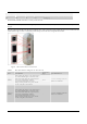
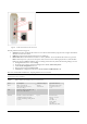
• RearpanelofSS‐300‐AT‐C‐60
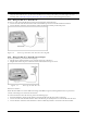
SS‐300‐AT‐C‐60isa802.11naccesspoint/sensordevicewithaCisco
compatibleconsoleport.Ithasfiveexternalantennaports‐
threeatthetopandtwoatthebottom.Itisadualradiodevicecapableofactingasanaccesspointorasensor.Thetopthree
antennasareforradio1andthebottomtwoantennasareforradio2.
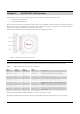
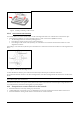
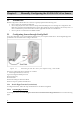
Thefront
paneloftheSS‐300‐AT‐C‐60hasLEDsthatindicatetheworkingofthedevice.
Figure 2. Front Panel of SS-300-AT-C-60
Note:LED5,thatisnotvisibleinthezoomed‐inviewintheabovefigure,isnotinuse.OnlyLED1,LED2,LED3andLED4areinuse.
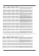
ThefollowingtableindicatesvariousdevicestatesusingtheLEDsonthedevice,whenthedeviceisinAPmode.
Table 1. LED details for SS-300-AT-C-60 in AP mode
LED1 or
Power
LED2 or
WLAN1
LED3 or
WLAN2
LED4 or
LAN
Description
Solid Green Any Any Solid Green
The AP is receiving power and is working
normally. The AP is connected to the Server.
Solid Green Off Slow Blink Slow Blink The AP upgrade is in progress.
Solid Orange Any Any Solid Green The AP is unable to get Ethernet link.
Solid Orange Any Any Fast Blink
The AP did not receive a valid IP address via the
DHCP.
Solid Orange Any Any Slow Blink The AP is unable to connect to the Server.
Off Off Off Off
The AP is not powered on or it is in the process
of starting up.
WLAN1andWLAN2LEDswillblinkwhenthereisactivityontherespectiveradios.
ThefollowingtableindicatesvariousdevicestatesusingtheLEDsonthedevice,whenthedeviceisinsensormode.