Installation Guide SS-300-AT-C-60 3x3 802.11abgn Access Point/Sensor ® AirTight Networks, Inc., 339 N. Bernardo Avenue, # 200, Mountain View, CA 94043 http://www.airtightnetworks.com Product documentation is being enhanced continuously based on customer feedback. To obtain a latest copy of this document, visit http://www.airtightnetworks.com/home/support.
This page has been intentionally left blank.
SS-300-AT-C-60 Access Point/Sensor Installation Guide
END USER LICENSE AGREEMENT Please read the End User License Agreement before installing the SS‐300‐AT‐C‐60 Access Point/Sensor. The End User License Agreement is available at the following location ‐.http://www.airtightnetworks.com/fileadmin/pdf/AirTight‐EULA.pdf. Installing the SS‐300‐AT‐C‐60 Access Point/Sensor constitutes your acceptance of the terms and conditions of the End User License Agreement. DISCLAIMER THE INFORMATION IN THIS GUIDE IS SUBJECT TO CHANGE WITHOUT ANY PRIOR NOTICE.
FEDERAL COMMUNICATIONS COMMISSION INTERFERENCE STATEMENT This equipment has been tested and found to comply with the limits for a Class B digital device, pursuant to part 15 of the FCC Rules. These limits are designed to provide reasonable protection against harmful interference in a residential installation. This equipment generates, uses and can radiate radio frequency energy and, if not installed and used in accordance with the instructions, may cause harmful interference to radio communications.
Canada, avis dʹIndustry Canada (IC) Cet appareil numérique de classe B est conforme aux normes canadiennes ICES‐003 et RSS‐210. Son fonctionnement est soumis aux deux conditions suivantes : (1) cet appareil ne doit pas causer dʹinterférence et (2) cet appareil doit accepter toute interférence, notamment les interférences qui peuvent affecter son fonctionnement.
Table of Contents Table of Contents CHAPTER 1 1.1 1.2 1.3 GETTING STARTED...................................................................................................................................1 BEFORE YOU BEGIN .......................................................................................................................................................1 HOW TO GET MORE INFORMATION .........................................................................................................
Table of Figures Table of Figures FIGURE FIGURE FIGURE FIGURE FIGURE FIGURE FIGURE FIGURE FIGURE FIGURE FIGURE FIGURE FIGURE FIGURE FIGURE FIGURE FIGURE FIGURE FIGURE 1. 2. 3. 4. 5. 6. 7. 8. 9. 10. 11. 12. 13. 14. 15. 16. 17. 18. 19. SS-300-AT-C-60 PACKAGE CONTENTS....................................................................................................................................... 2 FRONT PANEL OF SS-300-AT-C-60 ............................................................................
Chapter 1 1.1 Getting Started Before You Begin Thank you for purchasing SS‐300‐AT‐C‐60 from AirTight® Networks, Inc. The SS‐300‐AT‐C‐60 is a 3x3 802.11abgn Access Point / Sensor. Please read the EULA before installing the SS‐300‐AT‐C‐60. Installing the sensor constitutes your acceptance of the terms and conditions of the EULA mentioned above in this document. This product cannot be rented or leased–you are the sole owner of the product.
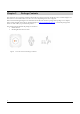
Chapter 2 Package Contents This chapter lists the components included in the SS‐300‐AT‐C‐60 device package. SS‐300‐AT‐C‐60 is a 3x3 802.11abgn Access Point / Sensor. It can function either as an AP or as a sensor depending on how it is configured. Please ensure that the following items are included in the SS‐300‐AT‐C‐60 device package. If the package is not complete, please contact AirTight® Networks, Inc. Technical Support at support@airtightnetworks.
Chapter 3 SS‐300‐AT‐C‐60 Overview This chapter provides an overview of the SS‐300‐AT‐C‐60 and describes in detail about the following. • • Front panel of SS‐300‐AT‐C‐60 Rear panel of SS‐300‐AT‐C‐60 SS‐300‐AT‐C‐60 is a 802.11n access point/sensor device with a Cisco compatible console port. It has five external antenna ports‐ three at the top and two at the bottom. It is a dual radio device capable of acting as an access point or a sensor.
Table 2. LED details for SS-300-AT-C-60 in sensor mode LED1 or Power LED2 or WLAN1 LED3 or WLAN2 LED4 or LAN Solid Green Solid Green Solid Green Solid Green The Sensor is receiving power and is working normally. The Sensor is connected to the Server. Solid Green Solid Green Fast Blink Solid Green The Sensor is performing troubleshooting on 802.11a/n. Solid Green Solid Green Slow Blink Solid Green The Sensor is performing intrusion prevention on 802.11a/n.
Solid Orange Any Any Slow Blink The AP is unable to connect to the Server. Off Off Off Off The AP is not powered on or it is in the process of starting up. WLAN2 LED will blink when there is activity on the AP radio. Note: If no channels are specified for monitoring and prevention on the sensor radio, the respective LED will have no activity and it will not glow.
Figure 4. Side Panel of SS-300-AT-C-60 The side panel has the following ports: • Serial port: Connects the SS‐300‐AT‐C‐60 device to serial terminal emulation programs such as Hyper Terminal for Windows or minicom for Linux. • USB port: Connects the SS‐300‐AT‐C‐60 device to a USB device. • Reset switch: Resets the SS‐300‐AT‐C‐60 device to factory defaults.
Chapter 4 Installing SS‐300‐AT‐C60 When the SS‐300‐AT‐C‐60 functions as a WIPS sensor, it monitors your network and communicates with the Server to guard your corporate network against over‐the‐air attacks. When the SS‐300‐AT‐C‐60 functions as an access point(AP), clients can connect to your corporate network in wireless mode through the APs. The SS‐300‐AT‐C‐60 must be plugged to your corporate network to perform the above operations.
1. Attach the metal slider to the back of the device using the two small screws. The slider should still be able to slide after the screws are tightened. Figure 5. Attaching the Metal Slider Make sure that the slide is left in the same position as shown above. Clip the metal ceiling bracket to a suitably‐located ceiling tile separator. Figure 6. Clipping the Metal Ceiling-bracket Slide the movable section into place and tighten the screw (found underneath) to secure it Figure 7.
Figure 8. Final positioning of the Sensor 4.2.1.2 Wall or Electrical Box Mounting To install the device on a wall or electrical box, use the mounting bracket that comes with the device. Follow these steps: 1. Following these guidelines, screw the mounting bracket to a wall or electrical box (NEMA enclosure): • The mounting bracket tabs should be pointing upward. • If mounting to drywall, use the 4 screws and 4 wall anchors. • If mounting to an EU electrical box (60.
4. Important: If DHCP is not enabled on a subnet, Sensors cannot connect to that subnet with zero configuration. If the DNS entry is not present on the DNS servers or you do not have the DHCP server running on the subnet, you need to configure the sensor manually. Refer to Manually Configuring SS‐300‐AT‐C‐60 as Sensor for details on manual configuration of Sensor. 4.2.3 Using SS‐300‐AT‐C‐60 with PoE To power on, and connect SS‐300‐AT‐C‐60 to the network using PoE, do the following. 1.
Figure 12. Connect SS-300-AT-C-60 to the network Wait for two minutes! Check the Status LEDs on the device. If all LEDs glow green, then the device is operational and connected to the SpectraGuard® Enterprise server. Log on to the SpectraGuard® Enterprise server through SSH. Run the ‘get sensor list’ command. You will see a list of all Sensors that are recognized by the SpectraGuard® Enterprise server. The Sensor is configured and ready to go.
Chapter 5 Manually Configuring the SS‐300‐AT‐C‐60 as Sensor Important: If the installation in InstallingSS‐300‐AT‐C‐60 was successful, stop! You do not need to configure the device manually. 5.1 Introduction Manual configuration of SS‐300‐AT‐C‐60 as a Sensor is typically required in the following cases: • Device needs to be configured in ND mode. • Sensor Only (SO) devices cannot connect to the SpectraGuard® Enterprise server through zero configuration.
Figure 14. Opening HyperTerminal Note: If you are using a Linux laptop, you can use minicom to connect to the Config Shell. 5.2.1.2 Defining a New HyperTerminal Connection Figure 15.
• Select an icon to identify the new connection. • Type the required name for the HyperTerminal connection in the Name field Click on the Connection Description dialog. 5.2.1.3 Specifying HyperTerminal Connection Details Figure 16. Specify HyperTerminal Connection Details • Select or enter the appropriate connection details. Click on the Connect To dialog. Note: The name of the serial port will change as per the settings of your computer. 5.2.1.
Figure 17. Edit Serial Port Settings for Sensor SS-300-AT-C-60 • Edit the serial port settings as follows or click to ensure proper communication between the Sensor and your computer. Bits per second: 115200 Data bits: 8 Parity: None Stop bits: 1 Flow control: None • Click on the COM Properties dialog. Press or on the HyperTerminal screen. 5.2.2 Log in and Change the Default Password Log in to the Config Shell using the user name config and password config.
• • • Sensor Mode: This is the default mode. In this mode, the device should be connected into a trunk port (802.1Q capable) on a switch. It then monitors multiple VLANs that are configured on that trunk port and are chosen by the user using the ND CLI. The wireless interface of the Sensor is enabled. Similarly, an SS‐300‐AT‐C‐60 can monitor upto 16 VLANs. ND Mode: This mode needs to be explicitly configured. In this mode, the device should be connected into a trunk port (802.1Q capable) on a switch.
Chapter 6 SS‐300‐AT‐C‐60 Config Shell Commands The following tables detail the SS‐300‐AT‐C‐60 config shell commands. Table 1.
set vlan config Configures list of VLANs and their network settings, to be monitored by ND or Sensor. set ipv6 config Sets IPv6 network settings. set mode Sets the mode to Sensor,Network Detector, or Sentry. set communication key Sets the Sensor-Server shared secret. You need to enter a hexadecimal value, of length 32, as the shared secret. It can be used instead of the ‘set communication passphrase’ command. Use this command if you are comfortable working with hexadecimals.
Chapter 7 SS‐300‐AT‐C‐60 Troubleshooting Following are the troubleshooting guidelines for SS‐300‐AT‐C‐60 in AP mode. Symptoms Diagnosis Solution LED1: Solid Orange LED4: Fast Blink The AP did not receive a valid IP address via the DHCP. The DHCP Server is unreachable. Restore the connectivity to the DHCP Server or set a static IP address via the HTTP interface or the Config Shell CLI. LED1: Solid Orange LED4: Slow Blink Unable to connect to the Server.
Symptoms Diagnosis Solution LED1: Solid Orange LED4: Fast Blink The Sensor did not receive a valid IP address via the DHCP. The DHCP Server is unreachable. Restore the connectivity to the DHCP Server or set a static IP address via the HTTP interface or the Config Shell CLI. LED1: Solid Orange LED4: Slow Blink Unable to connect to the Server. LED1: Solid Orange LED4: Solid Green The Ethernet cable is loose. It is probably disconnected from the network.
Chapter 8 Appendix A: Server Sensor Mutual Authentication The Sensor‐Server communication begins with a mutual authentication step in which the Sensor and Server authenticate each other using a shared secret. Sensor‐Server communication takes place only if this authentication succeeds. Once authentication succeeds, a session key is generated. All communication between the Sensor and Server from this point on is encrypted using the session key.