SpectraGuard Sensor Installation Guide
Disclaimer THE INFORMATION IN THIS GUIDE IS SUBJECT TO CHANGE WITHOUT ANY PRIOR NOTICE. AIRTIGHT NETWORKS, INC., IS NOT LIABLE FOR ANY SPECIAL, INCIDENTAL, INDIRECT, OR CONSEQUENTIAL DAMAGES WHATSOEVER (INCLUDING, WITHOUT LIMITATION, DAMAGES FOR LOSS OF BUSINESS PROFITS, BUSINESS INTERRUPTION, LOSS OF BUSINESS INFORMATION, OR ANY OTHER PECUNIARY LOSS) ARISING OUT OF THE USE OF OR INABILITY TO USE THIS PRODUCT.
End User License Agreement End User License Agreement This End User License Agreement (ìEULAî) governs the terms and conditions of use of AirTight products. If a Purchase Order has been issued by the Customer to AirTight for the use of this product, additional terms listed in the Purchase Order will also apply. In the event of a conflict between this EULA and a Purchase Order, the terms of the Purchase Order will prevail. 1.
End User License Agreement Customer, AirTight grants Customer a non-exclusive, non-transferable (except as provided in Section 9.5), nonsub licensable license during the term of this EULA, to install and execute such Software and Hardware for Customer's own business purposes. Each license is subject to the terms and conditions of this EULA, including but not limited to this Section 3 and Customer's obligation to pay the applicable license fees for the use of such Hardware and Software. 3.
End User License Agreement suppliers, including without limitation valuable trade secrets. The Software is licensed and not sold to Customer, and no title or ownership to such Software or the Intellectual Property Rights embodied therein passes as a result of this EULA or any act pursuant to this EULA.
End User License Agreement risk of loss or damage to any returned Hardware until such Hardware is received by AirTight at its premises. AirTight reserves the right to refuse to accept any returned Hardware that does not bear a tracking number on the outside of the carton or which otherwise does not comply with AirTight's return policies, procedures and instructions. 6.6 Disclaimer. Except for the express warranties in Sections 6.1, 6.2, and 6.
End User License Agreement Release of the Software other than the most current Release made available to Customer; or (d) any modification of the Hardware or Software by any person other than AirTight or its authorized agents. Customer will indemnify AirTight against all liability, damages and costs (including but not limited to reasonable attorneys' fees) resulting from or related to such a claim. 8.4 AirTight products may be capable of operating at frequencies beyond those allowed in your region.
End User License Agreement enforce this EULA, the prevailing party will be entitled to receive its attorneys' fees, court costs, and other collection expenses, in addition to any other relief it may receive. 9.10 Waivers and Modifications. All waivers must be in writing. Any waiver or failure to enforce any provision of this EULA on one occasion will not be deemed a waiver of any other provision or of such provision on any other occasion.
Table of Contents Table of Contents CHAPTER 1 PREFACE.............................................................................................................................1 1.1 1.2 BEFORE YOU BEGIN .......................................................................................................1 HOW TO GET MORE INFORMATION ..................................................................................1 CHAPTER 2 PACKAGE CONTENTS...........................................................
Table of Figures Table of Figures FIGURE 1 FIGURE 2 FIGURE 3 FIGURE 4 FIGURE 5 FIGURE 6 FIGURE 7 FIGURE 8 FIGURE 9 FIGURE 10 FIGURE 11 FIGURE 12 FIGURE 13 FIGURE 14 FIGURE 15 FIGURE 16 FIGURE 17 FIGURE 18 FIGURE 19 FIGURE 20 FIGURE 21 FIGURE 22 FIGURE 23 FIGURE 24 FIGURE 25 FIGURE 26 FIGURE 27 FIGURE 28 FIGURE 29 PACKAGE CONTENTS ...................................................................................................................
Preface Chapter 1 1.1 Preface Before you begin Thank you for purchasing SpectraGuard Sensor (also referred to as Sensor). SpectraGuard Sensor works in conjunction with a SpectraGuard Enterprise Server to provide an air-tight cover to your corporate network. It monitors the 802.11 a/b/g medium and provides information to the SpectraGuard Enterprise Server. Please read the EULA before installing the Sensor.
Package Contents Chapter 2 Package Contents This chapter gives you a list of the product package contents. Please make sure that the following contents form a part of the SpectraGuard Sensor package. If the package is not complete, please contact AirTight Networks, Inc., or return the package to the vendor or dealer where you purchased it.
Overview Chapter 3 Overview This chapter provides an overview of the SpectraGuard Sensor and describes in detail about the following: Port and Power Connections Status LEDs 3.1 Port and Power Connections The rear panel of the SpectraGuard Sensor has port and power connectors that enable you to power up the device and connect it to the network or a computer.
Overview Line Interface (CLI) sessions. Parity: None Stop Bits: 1 Flow Control: None Ethernet This enables the device to be connected to the wired LAN through a switch or a hub. This connection allows the SpectraGuard Sensor to communicate with the SpectraGuard Enterprise Server. RJ-45 10/100 Mbps/Ethernet Note: The Connection settings mentioned in Table 1 above are the same for Hyper Terminal and minicom. 3.
Overview Table 2 LED details LED LED Color Meaning of LED LED1 or Solid Green This indicates that the Sensor is receiving power and is working normally. There are no errors. Check LED2, LED3, and LED4 to determine the status of the device. Solid Yellow This indicates that the Sensor has encountered an error. Check LED2, LED3, and LED4 to determine the error. Off This indicates that the Sensor is not receiving power.
Overview LED4 Off If LED1 is green, it indicates an invalid state that should not occur. Try restarting the Sensor. If the problem persists, please contact support@airtightnetworks.net. Solid Green If LED1 is green, it indicates that the Sensor is scanning successfully on 802.11b/g (2.4 GHz frequency band). or If LED1 is yellow, it indicates that the Sensor is experiencing a software related error. This could be related to the Sensor software that connects to the SpectraGuard Enterprise Server. 802.
Installing SpectraGuard Sensor Chapter 4 Installing SpectraGuard Sensor Caution : The installation must be executed by technical staff. SpectraGuard Sensor is the probe that monitors your network and communicates with the SpectraGuard Enterprise Server to guard your corporate network against over-the-air attacks. The Sensor must be plugged to your corporate network to perform the above operations. Installing and configuring the SpectraGuard Sensor on the network is automatic.
Installing SpectraGuard Sensor Wait for two minutes! Check the Status LEDs. You will see LED1 turn yellow and LED2 turn green. This means that SpectraGuard Sensor is powered on correctly, and is waiting to be connected to the network. 4.2 Connecting to the Network Ensure that the SpectraGuard Enterprise Server is already running on your network. To connect SpectraGuard Sensor to the network, perform the following steps: 1.
Installing SpectraGuard Sensor Wait for two minutes! Check the Status LEDs. If all LEDs glow green, then the SpectraGuard Sensor is operational and connected to the SpectraGuard Enterprise Server. The SpectraGuard Sensor is configured and ready to go. Check your SpectraGuard Enterprise Console to ensure that this SpectraGuard Sensor has been detected. You need not read this installation guide further.
Manual Configuration of SpectraGuard Sensor Chapter 5 Manual Configuration of SpectraGuard Sensor Important! If the installation in Chapter 4 was successful, stop! You do not need to configure SpectraGuard Sensor manually. In this chapter you will learn how to manually configure SpectraGuard Sensor. The Sensor can be configured in two ways: Through the Web Interface (http) Through the Command Line Interface (CLI) You can choose either method to configure the SpectraGuard Sensor.
Manual Configuration of SpectraGuard Sensor 4. Change Discovery Settings Manual configuration can be done through a Web Interface (http) or Command Line Interface (CLI). 5.3 Configuring SpectraGuard Sensor through Web Interface (http) Configuration using Web Interface is done using the network connection or using the crossover cable connected between your machine and the Sensor.
Manual Configuration of SpectraGuard Sensor Figure 7 Login Screen To log in, you have to perform the following steps: 1. Set your laptop as per the same subnet settings and a different IP address (ignore if already done). 2. Type the correct IP address obtained from the DHCP Server in the Web Interface, for Web configuration using the Ethernet cable. Type the address 192.168.1.245 in the Web Interface, for Web (http) configuration using the crossover cable. 3.
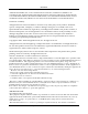
Manual Configuration of SpectraGuard Sensor Figure 8 Password Settings Screen The Password Settings Screen as shown in Figure 8 above appears by default and allows the user to change the password. Enter the old password and the new password and click Apply. Note: If you do not change the password the first time you log in, then the Password Settings Screen appears every time you log into SpectraGuard Sensor. Once you change the password this screen does not reappear.
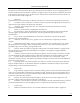
Manual Configuration of SpectraGuard Sensor settings are required so that the SpectraGuard Sensor can communicate with the SpectraGuard Enterprise Server. Figure 10 Network Settings Screen There are three main sections under the Network Settings tab. MAC Settings IP Address Settings Route Settings MAC Settings Ethernet MAC address shows the Media Access Control (MAC) address of the SpectraGuard Sensor Ethernet Interface. This is a unique address assigned to every network interface.
Manual Configuration of SpectraGuard Sensor Get IP over DHCP: This field is checked by default. This enables SpectraGuard Sensor to get an IP address automatically from a DHCP Server. If this field is unchecked, you can set the IP address manually. IP Address: This field can be set only if the Get IP over DHCP field is unchecked. This field sets the IP address of the SpectraGuard Sensor. The IP address should belong to the network segment on which this SpectraGuard Sensor is to be connected.
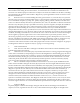
Manual Configuration of SpectraGuard Sensor Figure 11 Discovery Settings Screen There are two main sections under Discovery Settings: Auto Discover SpectraGuard Enterprise Server Manually Discover SpectraGuard Enterprise Server Auto Discover SpectraGuard Enterprise Server You can set up the SpectraGuard Sensor to automatically discover and connect to the SpectraGuard Enterprise Server.
Manual Configuration of SpectraGuard Sensor Clicking Reset to Factory Defaults resets the configuration parameters to the factory default settings. In this case, all the configuration settings, including the password settings will be restored to factory defaults. Click this button, only when you want SpectraGuard Sensor to behave like a brand new SpectraGuard Sensor. 5.
Manual Configuration of SpectraGuard Sensor Figure 13 Opening HyperTerminal Note: If you are using a Linux laptop, you can use minicom to connect to the Command Line Interface (CLI). 2. Defining a New Connection Once HyperTerminal opens, Figure 14 will appear by default. You have to name the new connection, so that your connection is recognized. You can also select an icon to identify your new connection.
Manual Configuration of SpectraGuard Sensor Figure 14 New HyperTerminal Connection Type the desired name for the connection. For example, ëSpectraGuard Sensorí under the Name field and click OK. 3. Adding Connection Details Select the appropriate serial port from the Connect using drop-down list and click OK.
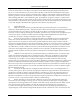
Manual Configuration of SpectraGuard Sensor Note: The name of the serial port will change as per the settings of your machine. 4. Editing Port Settings Enter the following values under the COM Properties window to ensure proper transmission. Bits per second: 9600 Data bits: 8 Parity: None Stop bits: 1 Flow control: None Figure 16 HyperTerminal Port Settings After selecting these settings, click OK. The Command Line Interface is now ready. 5.4.
Manual Configuration of SpectraGuard Sensor The passwd command changes the password of the default user ëconfigí. The default password is ëconfigí. Type the following commands (shown in bold) to change the Password Settings. $ login: config Password: passwd Changing password Password changed. *Please reboot sensor for changes to take effect* The following screen is an example from a live session.
Manual Configuration of SpectraGuard Sensor $ setdhcpip Stopping SpectraGuard Sensor... Getting IP over dhcp... Enter Route Settings or press Enter to skip settings routes Route Settings: Network ID: Applying Changes... Ethernet MAC Address = 00:11:74:20:10:C4 Boot IP Protocol = dhcp IP=192.168.3.58 Mask=255.255.255.0 Gateway= Note: If IP address assignment via DHCP fails, the default values assigned are as follows: IP address = 192.168.3.58 Net Mask = 255.255.255.
Manual Configuration of SpectraGuard Sensor The default gatewayóWhen Ethernet traffic from the subnet is forwarded to another network, it is sent through the Gateway. Enter the Gateway IP Address for the subnet on which this SpectraGuard Sensor is to be connected. Route SettingsóNormally, you do not need to specify the route settings.
Manual Configuration of SpectraGuard Sensor Figure 19 5.4.4 Changing network settings using the setstaticip command Step 4: Change Discovery Settings Discovery Settings set up the discovery of the SpectraGuard Enterprise Server by the SpectraGuard Sensor. These settings must be manually configured only if SpectraGuard Sensor is unable to locate the SpectraGuard Enterprise Server. Commands to change Discovery Settings Type the following commands to change the Discovery Settings.
Manual Configuration of SpectraGuard Sensor The following screen is an example from a live session. Figure 20 5.4.5 Changing Discovery Settings using the editconfig command Other Commands The following commands are optional and can be used to check the working of the SpectraGuard Sensor. These commands are provided for information only and it is not necessary to use these commands.
Manual Configuration of SpectraGuard Sensor server_ipóThis parameter signifies the IP address of the SpectraGuard Enterprise Server to which the SpectraGuard Sensor connects. This is valid and is displayed only if auto_discovery="n", i.e., multicasting is disabled. Default IP Address = 255.255.255.255 server_idóThis parameter signifies the Server ID of the SpectraGuard Enterprise Server to which the SpectraGuard Sensor connects. This is valid and will be displayed only if auto_discovery="y", i.e.
Manual Configuration of SpectraGuard Sensor Figure 23 Resetting to factory default settings using the resetfactory command Viewing the status of SpectraGuard Sensor statusóThis command shows the current status of the Sensor. The two possible states are "Not Running" or "Running". Figure 24 status command Viewing the status of the SpectraGuard Sensor software veróThis command displays the version of the software running on the Sensor.
Manual Configuration of SpectraGuard Sensor Figure 27 sensord_restart command Rebooting the Sensor rebootóThis command causes the Sensor to physically reboot. You do not need to reconfigure SpectraGuard Sensor after the reboot. Exiting the shell exitóThis command causes the shell to exit and the login screen to appear. Figure 28 exit command Viewing the available commands helpóThis command displays the list of available commands.
Troubleshooting Chapter 6 Troubleshooting Symptoms Diagnosis Solution LED1: Yellow Not getting a DHCP address. The DHCP Server is down. Either bring up the DHCP Server or set a static IP address via the Web (http) or Command Line Interface. Unable to connect to the SpectraGuard Enterprise Server.