
User's Guide
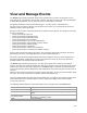
Table Of Contents
- About This Guide
- Introduction
- AirTight Management Console Configuration
- Configure Language Setting
- Configure Time Zone and Tag for Location
- User Management
- User Authentication
- Wireless Intrusion Prevention System
- Manage WiFi Access
- Configure Device - Server Communication Settings
- Manage Policy Templates
- Manage Authorized WLAN Policy
- View High Availability Status for Server
- View/Upgrade License Details
- Manage Look and Feel of Reports
- Configure NTP
- Configure RF Propagation Settings
- Configure Live RF View Setting
- Configure Location Tracking
- Manage Auto Location Tagging
- Set up and Manage Server Cluster
- Manage Vendor OUIs
- Manage Device Template
- Configure SMTP Settings
- View System Status
- Upgrade Server
- Configure Auto Deletion Settings
- Manage Audit Log Settings
- Configure Integration with Enterprise Security Management Servers
- Manage WLAN Integration
- Manage AirTight Mobile Clients
- AirTight Mobile Settings
- Manage AirTight Mobile Clients
- Add AirTight Mobile Group Manually
- Edit AirTight Mobile Group
- Attach Policy to AirTight Mobile Group
- Overwrite Existing Policy for AirTight Mobile Group
- Detach Policy from AirTight Mobile Group
- View AirTight Mobile Group Policy in HTML Format
- View AirTight Mobile Group Policy in XML Format
- Activate Automatic Client Grouping
- Apply Default Policy to New Groups
- Print List of AirTight Mobile Groups for Location
- Delete AirTight Mobile Group
- Dashboard
- Devices
- AirTight Devices
- Device Properties
- View Visible LANs
- View Visible APs
- View Visible Clients
- View Active APs
- View Active Clients
- View AirTight Device Events
- View Channel Occupancy
- View Interference
- View Mesh Network Links
- Search AirTight Devices
- Sort AirTight Devices
- Change Location
- Print AirTight Device Information for Location
- Reboot Device
- Troubleshoot Device
- Upgrade or Repair Device
- Enable Pagination for AirTight Device Listing and Set Page Size
- Disable Pagination for AirTight Device Listing
- Add Custom Filter
- Edit Custom Filter
- Delete Custom Filter
- Delete Device
- Monitor Clients
- View Client Properties
- View Recently Associated APs/Ad hoc networks
- View Events related to Client
- View Client Retransmission Rate Trend
- View Devices Seeing Client
- View Client Average Data Rate
- View Client Traffic
- Change Client Location
- Quarantine Client
- Disable Auto Quarantine/Exclude Device from Intrusion Prevention Policy
- Add to banned list
- Classify / Declassify as Smart Device
- Change Client Category
- Reset Data Transmitted by Client
- Locate Client
- View Recently Probed SSIDs
- Troubleshoot Client
- Debug Client Connection Problems
- Download Connection Log
- Delete Connection Log History
- Enable Pagination for Client Listing and Set Page Size
- Disable Pagination for Client Listing
- Add Custom Filter
- Edit Custom Filter
- Delete Custom Filter
- Print Client List for Location
- Delete Client
- Spectrogram
- Monitor Access Points (APs)
- View AP Properties
- View Recently Associated Clients
- View AP Utilization
- View AP Associated Clients
- View AP Traffic
- View AP Average Data Rate
- View Devices Seeing AP
- View AP Events
- Change AP Location
- Locate AP
- Quarantine an AP
- Change AP Category
- Disable Auto Quarantine
- Add to banned list
- Sort APs
- Filter AP Details
- Search APs
- Enable Pagination for AP Listing and Set Page Size
- Disable Pagination for AP Listing
- Add Custom Filter
- Edit Custom Filter
- Delete Custom Filter
- Print AP List for Location
- Merge APs
- Split AP
- Troubleshoot AP
- Delete AP
- Monitor Networks
- AirTight Devices
- Manage Locations and Location Layout
- Define Location Tree
- Add Location
- Edit Location
- Move Location
- Delete Location
- Search Locations
- Add Layout
- Edit Layout
- Delete Layout
- Show / Hide Location List
- Show/Hide Devices on Location Layout
- Place Devices/Locations on Location Layout
- Remove Devices/Locations from Location Layout
- View RF Coverage / Heat Maps
- Calibrate RF Views
- Zoom in / Zoom out Layout
- Adjust the Layout Opacity
- Add Note
- Edit Note
- Move Note
- Hide Notes
- Show Notes
- View Mesh Topology
- Hide Mesh Topology
- View and Manage Events
- View Events for Location
- View Deleted Events for Location
- Change Event Location
- Acknowledge Event
- Turn on Vulnerability Status for Event
- Turn off Vulnerability Status for Event
- Mark Event as Read
- Mark Event for Deletion
- Enable Pagination for Event Listing and Set Page Size
- Disable Pagination for Event Listing
- Add Custom Filter
- Edit Custom Filter
- Delete Custom Filter
- Print Event List for Location
- Forensics
- Reports
- Glossary of Icons

AirTight Management Console User Guide
224
When you change the Minimum Signal Decay exponent, Maximum Signal Decay exponent, Signal Decay
Slope (Beta), and Signal Decay Inflection (Alpha) the RF view and location tracking for unobstructed
regions is affected. In the obstructed regions, only Location Tracking is affected, RF view is not affected.
When you calibrate manually, the graph is automatically updated.
To calibrate RF views automatically, do the following.
1.
Go to Locations.
2.
From the location tree, select the location for which you want to calibrate RF views.
3.
Generate the RF Coverage/heatmap using the steps explained in the View RF Coverage/Heat Maps
section
4. Clicking the Calibration link. The Calibration dialog box appears.
5.
To calibrate automatically, click Calibrate under Automatic Calibration. The graph is updated when
you click Calibrate.
6.
To calibrate manually, change the values of the Signal Decay Slope (Beta) and the Signal Decay
Inflection (Alpha). The system uses these parameters when computing the RF and defines the region
around the transmitter that is unobstructed.
7.
Adjust the confidence.
8.
Click OK or Apply to complete calibration if you have adjusted the parameters manually such that the
two curves are parallel (but not coinciding).
Note: You can change the intrusion detection display threshold and the intrusion prevention display
threshold from Configuration>System>Advanced Settings>Live RF View Settings.
Zoom in / Zoom out Layout
The Zoom slider is to the left of the Locations page. Move the Zoom slider up, to zoom in the layout.
Move the Zoom slider down, to zoom out the layout.
Select an appropriate resolution for rendering of heat maps. A lower resolution would mean a much faster
rendering, although with a high pixelization effect. High resolution would mean a much slower rendering
due to a large number of pixel cells for which values are being calculated. You can zoom in to a maximum
of 400% of the actual size. You can zoom out to a minimum of 25% of the actual size of the layout image.
Adjust the Layout Opacity
Move the Opacity slider to the right and left to adjust the opacity of the layout. This slider is on the top
right side of the Locations page.
•
Decrease the image opacity to comprehend the RF coverage in a better way.
•
Increase the image opacity to pinpoint exact device placement information.
Add Note
You can add notes to the location layout. These notes could be additional explanatory text or comments
related to the devices or the layout, in general.
To add a note to a location layout, do the following.
1.
Go to Locations.
2.
Select the desired location. Ensure that the layout has been added. If the layout is not added, add a
layout first.