
Installation Instructions


1.10.3Trim Completes the Job
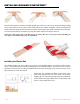
Reducer Profile
First, saw the profile to the correct length and use the cutting tool to cut
away piece A to obtain an adaptor profile. Please note: The edge of the cut
profile can be very sharp. Be sure to wear gloves when handling the raw
edges, and sand the edges prior to installation. Next, mark the ground to
indicate how far the edge of the floor will extend. Allow the underlay to
extend to just before this line; it is better to fit the rail in which the adaptor
will be clamped on top of the subfloor. There must be a sufficient expansion
gap between the raised legs of the rail and
the floor-—between 5/16’s to 7/16’s inch.
Attached the plastic rail to the subfloor with
the long lip in the floor direction. Gently
press from one side of the rail to the other,
and then press against the floor.
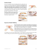
Expansion Profile/T-Molding
First cut the profile to the correct length. Use the knife to cut away pieces A
and B to obtain the expansion profile/T-molding. Please note: The edge of
the cut profile can be very sharp. Be sure to wear gloves when handling
the raw edges, and sand the edges prior to installation.
While installing the floor, be sure to allow sufficient space between the two
surfaces that will be joined by the molding. Be sure to take into account
the expansion gap between the raised legs of the plastic rail and the floor.
You’ll insert the molding into this rail.
Cut the plastic rail to the proper length and place it in the middle of the open area between the two floor
surfaces. Gently press from one side of the rail to the other, and then press against the floor.