
Specifications


Before Connection to Power Supply
• Remove all packing.
• Check equipment and parts for damage. Report any damage immediately to the carrier and
distributor.
• Remove protective plastic coating from the side panels.
• Check that the available power supply is correct to that shown on the rating plate located on the
right-hand side panel.
E89MS 110-120 Volts A.C, 60 Hz, 1P+N+E, 1.50 kW, 12.5 A @ 120V
E89M/MS 208-220 Volts A.C, 50/60 Hz, 1P+N+E, 1.45 kW, 6.5 A @ 220V
E89M/MS 220-240 Volts A.C, 50/60 Hz, 1P+N+E, 1.70 kW, 7.1 A @ 240V
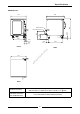
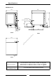
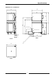
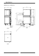
Location
• To ensure correct ventilation for the and controls the following minimum installation
clearances are to be adhered to:
Electrical Connection
• E89M/MS provers are supplied fitted with cords. Ensure unit is fitted with correct cord and plug.
• To access the electrical connection terminal block, grounding lug and strain relief, remove the
right hand side panel.
WARNING - THIS APPLIANCE MUST BE EARTHED / GROUNDED
Water Connection (Auto Fill Models Only)
• A cold water supply should be fitted to the water inlet which is located near the rear of the right
hand side of the unit.
• A connection elbow and sealing washer is supplied with this unit for direct connection of a ½” ID
hose, and is recommended for easy installation and service.
• Connect water supply - Max inlet pressure 550kPa / 80psi.
• Turn on water supply to check for leaks.
Rack Width
• The E89 prover has been designed to accept either 460mm (18”) or 405mm (16”) wide trays or 1/1
GN,
1
/
2
/1 GN trays.
• The prover comes factory set for 460mm (18”) trays, a rack spacer kit (Part no. 025685) is
required to change to 405mm (16”) trays or Gastronorm pans.
3
Installation
Installation Requirements
It is most important that this prover / holding cabinet is installed correctly and that
operation is correct before use.
Installation shall comply with local electrical, health and safety requirements.
Rear 0 mm / 0 ”
Left-hand side 0 mm / 0 ”
Right-hand side 25 mm / 1 ”
gpd.sunwayinfo.com.cngpd.sunwayinfo.com.cn