ay in fo . co m .cn INSTALLATION / OPERATION MANUAL gp d.
MANUFACTURED BY Moffat Limited PO Box 10001 Christchurch New Zealand Ph: (03) 389 1007 Fax: (03) 389 1276 WORLD-WIDE BRANCHES UNITED KINGDOM Blue Seal Units 6-7, Mount Street Business Park Mount Street, Nechells Birmingham B7 5QU Ph: (121) 327 5575 Fax: (121) 327 9711 UNITED STATES Moffat Inc 3765 Champion Blvd Winston-Salem North Carolina 27115 Ph: (336) 661 0257 Fax: (336) 661 9546 .
Contents Introduction ........................................................................................................2 Installation ..........................................................................................................3 Before Connection Location Electrical Connection Water Connection (Auto Fill Models Only) Rack Width Stacking with Convection Oven Specifications.....................................................................................................5 Operation ....
Introduction We are confident that you will be delighted with your E89M/MS PROVER / HOLDING CABINET, and it will become a most valued appliance in your commercial kitchen. A new oven can seem very complex and confusing at first glance. To ensure you receive the utmost benefit from your new Prover, there are two important things you can do. Firstly Please read the instruction book carefully and follow the directions given. The time taken will be well spent. Secondly gp d. su n w ay in fo . co m .
Installation Installation Requirements It is most important that this prover / holding cabinet is installed correctly and that operation is correct before use. Installation shall comply with local electrical, health and safety requirements. Before Connection to Power Supply • Remove all packing. • Check equipment and parts for damage. Report any damage immediately to the carrier and distributor. • Remove protective plastic coating from the side panels.
Installation Stacking with Convection Oven The E89M/MS prover is supplied standard for stand alone use. • Optionally, the E89M/MS prover can be double stacked, or combined underneath a TURBOFAN E32M/MS convection oven as a complete unit. For this a stacking kit is required. • For installation of the stacking kit, refer to the instructions provided with the kit. gp d. su n w ay in fo . co m .
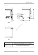
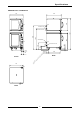
Specifications E89M Prover 710 810 900 WATER ENTRY 200 355 66.5 ELECTRICAL ENTRY 515 51.5 117.5 610 68 Front fo . co m .cn Side gp d. su n w ay in 710 Plan Electrical Connection Cold Water Connection (Auto Fill Models Only) 208-220 Volts A.C, 50/60 Hz, 1P+N+E, 1.45 kW, 6.5 A @ 220V 220-240 Volts A.C, 50/60 Hz, 1P+N+E, 1.70 kW, 7.
Specifications E89MS Prover 710 810 900 WATER ENTRY 66.5 200 355 ELECTRICAL ENTRY 515 51.5 117.5 610 68 Front co m .cn Side gp d. su n w ay in fo . 710 Plan Electrical Connection Plan Cold Water Connection (Auto Fill Models Only) 110-120 Volts A.C, 60 Hz, 1P+N+E, 1.50 kW, 12.5 A @ 120V 208-220 Volts A.C, 50/60 Hz, 1P+N+E, 1.45 kW, 6.5 A @ 220V 220-240 Volts A.C, 50/60 Hz, 1P+N+E, 1.70 kW, 7.
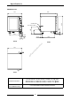
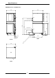
Specifications E89M Prover / E32M Oven 710 MWS 1 645 810 MWS WATER ENTRY E 1 E WATER ENTRY MWS 900 1105 1260 1647 ELECTRICAL ENTRY MWS 66.5 200 355 ELECTRICAL ENTRY .cn 515 m 51.5 fo . in gp d. su n w ay Front 710 1 E 610 co 117.
Specifications E89MS Prover / E32MS Oven 710 MWS 1 645 810 MWS WATER ENTRY E 1 E 1105 WATER ENTRY ELECTRICAL ENTRY 66.5 MWS .cn 200 355 MWS 900 1260 1647 ELECTRICAL ENTRY m 515 co 51.5 117.5 in gp d. su n w ay Front 710 1 E 610 fo .
Operation Operation Guide 89 Description of Controls Function O PROOF HOLD Unit is off Unit is in proving mode (indicator illuminates) Unit is in holding mode (indicator illuminates) F OO PR Thermostat m .cn Temperature range 0 - 85°C (32 - 185°F). 20 - 40°C (65 - 105°F) Proving range 65 - 85°C (150 - 185°F) Holding range Indicator illuminates when the elements are cycling ON to maintain set temperature. (Controls the cabinet air temperature) fo .
Operation Operating in PROOF Mode Ensure that power is supplied to the unit and the water trough is filled It is recommended that the prover operates empty before loading with product - Warm days up to 10 minutes - Cool days up to 30 minutes 1. Ensure water tank is filled with water Standard models: Open the prover door and fill the water tank located at the front of the right hand side rack. The tank should be filled to 20mm (¾”) from the top of the tank.
Operation Problem Solving Product collapses When using frozen dough which collapses or shrinks in the oven after proving, this is caused by too much proving. Reduce the proving time for the next batch. Dry product The dough piece in the prover should never be dry to the touch. A moist, firm and silky membrane should cover the dough piece during proving. Wet product The dough piece in the prover should not be wet to touch whilst proving and should not adhere to fingers.
Operation Operating in HOLD Mode Ensure that power is supplied to the unit and the water trough is filled It is recommended that the cabinet operates empty before loading with product - Warm days up to 10 minutes - Cool days up to 30 minutes 1. Set function to HOLD Indicator light will illuminate when the switch is in the “HOLD” position. 2. Set thermostat to desired holding temperature Indicator light will illuminate when the elements are cycling on to maintain set temperature. 3.
Cleaning Cleaning Guidelines Caution: ALWAYS TURN OFF THE POWER SUPPLY BEFORE CLEANING. THIS UNIT IS NOT WATER PROOF. DO NOT USE WATER JET SPRAY TO CLEAN INTERIOR OR EXTERIOR OF THIS UNIT. Cabinet Clean with a good quality stainless steel cleaning compound. Harsh abrasive cleaners may damage the surface. Side racks To remove, take hold of the centre rung and lift upwards to disengage the rack key-holes from the hanger studs. To replace, hold horizontally, engage keyholes onto studs and push down.
Trouble-shooting Unit is in HOLD mode Switch unit to PROOF mode. (Humidity is only generated in PROOF mode). No water in trough. Fill with water. Overloading of cabinet. Reduce batch size. Door opened unnecessarily. Do not open unnecessarily. Tray in way of door. Correctly position tray in rack. in fo . co m .cn Rotate switch. Indicator will illuminate. ay Door does not close. The power switch on the cabinet is off. w Slow recovery. Turn on. su n No humidity.
Spare parts Replacement Part List Controls 022789 020823 022787 024527 020823 021472 020849 023857 022788 Function Switch Knob (Function Switch) Thermostat (Cabinet Temperature) Thermostat (Humidity) Knob (Temperature Thermostat) Knob (Humidity Thermostat) Neon Indicator (208-240V) Neon Indicator (110V-120V) Thermometer (Dual °C & °F) Auto Fill Option 020851 021617 021534 021535 022250 022250 Solenoid Valve (208-240V) Solenoid Valve (110-120V) Relay (208-240V) Relay (110-120V) Float Switch (208-240V) Fl
4 3 P3 2 P2 1 P1 4 PWR P4 GROUND 3 OF PRO P3 2 HOL D 1 FUNCTION SWITCH PROOF HOLD OFF P2 P1 P4 P3 P2 P1 P4 4 3 2 1 4 P4 P2 P1 3 P3 2 1 FUNCTION SWITCH OPERATION HOLD ELEMENT 600W 110V 800W 240V gp d. 16 in DRY ELEMENT 600W 110V 800W 240V PILOT LIGHT .cn m co fo .
GROUND 2 P2 2 P2 1 P1 1 P1 PRO PWR P4 P4 4 P4 4 P4 4 PROOF HOLD OFF 4 3 2 1 HOLD ELEMENT 600W 110V 800W 240V OF D HO L P3 P2 P3 3 P3 3 P3 3 FUNCTION SWITCH P2 P1 P1 2 1 FUNCTION SWITCH OPERATION 17 DRY ELEMENT 600W 110V 800W 240V PILOT d. LIGHT THERMOSTAT 2 1 gp .cn HUMIDITY ELEMENT 600W 110V 800W 240V POWER PILOT LIGHT HUMIDITY THERMOSTAT m 2 co in 1 fo .
gp d. in ay w su n .cn m co fo .
gp d. in ay w su n .cn m co fo .