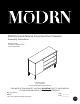
MŌDRN Scandi Minimal Finna One Door Credenza Assembly Instructions White/Light Oak model# HYN-FNMDCR-WH UPC 677446152664 Customer Service: 1.877.436.7290 customersupport@tenspringstreet.com THIS INSTRUCTION BOOKLET CONTAINS IMPORTANT SAFETY INFORMATION. PLEASE READ AND KEEP FOR FUTURE REFERENCE.
PRE-ASSEMBLY PREPARATION: DO NOT LET CHILDREN PLAY IN OR AROUND THE UNIT DUE TO THE POSSIBLE RISK OF FINGER ENTAPMENT • • • • • • Please read through this instruction before beginning assembly. Two adults assembly is recommended. Clear out the space for assembly and lay out all parts base on Parts List, extra room will allow you to easily determine if all the pieces are present. Save all packing materials until assembly is complete to avoid accidentally discarding smaller parts or hardware.
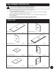
PARTS LIST: Right Back Panel (I) QTY: 1 Door (K) QTY: 1 Leg (J) QTY: 4 3/13
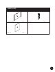
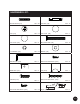
HARDWARE LIST: Wooden Dowel (H1) QTY: 20 Cam Bolt (H2) QTY: 14 Cam (H3) QTY: 14 Cam Cover (H4) QTY: 4 Cam Cover (H5) QTY: 2 Lock Washer (H7) QTY: 12 Washer (H8) Allen Wrench (H9) QTY: 1 15mm Pan Head Screw (H10) QTY: 31 Metal Plate (H11) QTY: 3 Pull (H12) QTY: 1 Pull Bolt (H13) QTY: 1 32mm Flat Head Screw (H14) QTY: 2 15mm Flat Head Screw (H15) QTY: 12 Hinge (H16) M6 x 50mm Bolt (H6) QTY: 12 QTY: 12 QTY: 2 4/13
HARDWARE LIST: Shelf Pin (H17) QTY: 4 5/13
CAM LOCK INSTRUCTION This product is assembled with a cam lock set. STEP 1: Insert Cam lock into the cam lock hole of panel I. Cam lock arrow should be pointing towards the cam lock dowel insertion hole. STEP 2: Insert wooden dowel into panel II. STEP 3: Connect panel I and panel II by CAM LOCK HOLE CAM LOCK CAM LOCK DOWEL inserting the cam lock dowel through the hole to where the cam lock arrow is pointing. STEP 4: Press panel I and panel II together.
STEP-BY-STEP ASSEMBLY: 1 STEP 1: Insert H6 into panel D. Make sure the bolts go through the pre-drilled holes properly. Do not over tighten bolts. Anti-tip Restraint is REQUIRED in order to complete construction of this product. When properly installed, this hardware can provide protection against the unexpected tipping of furniture. 2 STEP 2: Carefully tap small wooden dowels into place. Leave 1/2” of the dowels sticking out. Make sure the bolts go through the pre-drilled holes properly.
STEP-BY-STEP ASSEMBLY: 3 4 STEP 3: Carefully tap small wooden dowels into place. Leave 1/2” of the dowels sticking out. Insert H2 into panel F. Refer to page 6 on how to use the cam lock system. Ensure all hardware pieces are properly tightened. STEP 4: Carefully tap small wooden dowels into place. Leave 1/2” of the dowels sticking out. Insert H2 into panel C. Refer to page 6 on how to use the cam lock system. Ensure all hardware pieces are properly tightened.
STEP-BY-STEP ASSEMBLY: 5 6 STEP 5: Carefully tap small wooden dowels into place. Leave 1/2” of the dowels sticking out. Make sure the bolts go through the pre-drilled holes properly. Do not over tighten bolts. STEP 6: Insert H2 into panel A. Refer to page 6 on how to use the cam lock system. Ensure all hardware pieces are properly tightened. Carefully tap small wooden dowels into place. Leave 1/2” of the dowels sticking out.
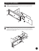
STEP-BY-STEP ASSEMBLY: 7 STEP 7: Begin by installing all of the screws along one edge of the back panel. Next, using a square or tape measure, make sure that the case is square. (if using a tape measure, the distance from one corner, diagonally to the other corner should be the same in both directions.) Install the remaining screws, starting with the corners. hole for anti-tip strap 8 STEP 8: Insert shelf supports into desired holes. Different holes accommodate different shelf heights.
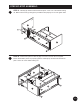
STEP-BY-STEP ASSEMBLY: 9 STEP 9: Make sure the screws go through the pre-drilled holes properly. Do not over tighten screws.
ANTI-TIP RESTRAINT 2 5 1 4 3 1 x2 x1 x1 x1 x1 1 . Wa s h e r 2 . Wa l l Anchor 3 . Wa l l Screw 4 . Tr u s s Head Screw 5 . Wa l l Strap Assembly Instructions: STEP 1: Attach wall strap to product using provided screw. STEP 2: Position against wall. STEP 3: Mark position of strap hole on wall. Drill 1/4” hole.
PRE-ASSEMBLY PREPARATION: WARNING: Do not exceed the maximum load capacity. Exceeding the maximum load capacity may result in collapse and possible injury. . 7 kg 45 lb lb s. g s. e te ne le ra vi l 50 si us lb on e s. /2 us / 2. e • Your complete satisfaction is our number 1 priority. Our product is designed and manufactured to meet the highest quality of standards.
MŌDRN Aparador de Una Puerta Escandinavo Minimalista Finna Instrucciones de Ensamble blanco/roble claro model# HYN-FNMDCR-WH UPC 677446152664 Servicio al Cliente: 1.877.436.7290 customersupport@tenspringstreet.com ESTE MANUAL DE INSTRUCCIONES CONTIENE INFORMACIÓN IMPORTANTE DE SEGURIDAD. POR FAVOR LEA Y GUARDE PARA REFERENCIA FUTURA.
PREPARACIÓN DE PRE-MONTAJE: NO PERMITA QUE LOS NIÑOS JUEGUEN ALREDEDOR DE LA UNIDAD POR EL POSIBLE RIESGO DE ATRAPAMIENTO DE LOS DEDOS • • • • • • Por favor, lea estas instrucciones antes de comenzar el ensamblaje. Se recomienda que el montaje se lleve a cabo por dos adultos. Despeje el espacio donde se llevará a cabo el montaje y coloque todas las piezas y la base de la Lista de Piezas, el espacio adicional le permitirá determinar fácilmente si todas las piezas están presentes.
LISTA DE PARTES: Panel Posterior Derecho (I) QTY: 1 Puerta (K) QTY: 1 Pata (J) QTY: 4 3/13
LISTA DE ARTÍCULOS DE FERRETERÍA: Clavija De Madera (H1) QTY: 20 Tornillo de Leva (H2) QTY: 14 Leva (H3) QTY: 14 Cubierta del Tornillo (H4) QTY: 4 Cubierta del Tornillo (H5) QTY: 2 Arandela Fijadora (H7) QTY: 12 Arandela (H8) Llave Allen (H9) QTY: 1 15mm Tornillo de Cabeza de Noria (H10) QTY: 31 Placa De Metal (H11) QTY: 3 Perilla (H12) QTY: 1 19mm Perno de Perilla (H13) QTY: 1 32mm Tornillo de Cabeza Plana (H14) QTY: 2 15mm Tornillo de Cabeza Plana (H15) QTY: 12 Bisagra (H16) M6*50m
LISTA DE ARTÍCULOS DE FERRETERÍA: Pasador para Repisa (H17) QTY: 4 5/13
INSTRUCCIONES PARA LAS TRABAS DE LEVA Este producto se ensambla con un juego de trabas de leva. PASO 1: Inserte la traba de leva en el orificio para la traba de leva del panel I. La flecha de la traba de leva debe apuntar hacia el orificio de inserción de la clavija de la traba de leva. PASO 2: Inserte una clavija de madera en el panel II.
ENSAMBLAJE PASO A PASO: 1 PASO 1: Inserte H6 en el panel D. Cerciórese que los pernos pasen por los agujeros pretaladrados de manera apropiada. No sobreapriete los pernos. Se REQUIERE el control antivuelco para completar la construcción de este producto. Una vez que esté correctamente instalado, esta pieza puede brindar protección contra el inesperado vuelco de los muebles. 2 PASO 2: Con cuidado golpee las clavijas de madera en su lugar. Deje un saliente de 1.27 cm (½”) en las clavijas.
ENSAMBLAJE PASO A PASO: 3 4 PASO 3: Con cuidado golpee las clavijas de madera en su lugar. Deje un saliente de 1.27 cm (½”) en las clavijas. Inserte H2 en el panel F. Consulte la página 6 sobre cómo usar el sistema de trabas de leva. Asegúrese de que todas las piezas metálicas estén bien ajustadas. PASO 4: Con cuidado golpee las clavijas de madera en su lugar. Deje un saliente de 1.27 cm (½”) en las clavijas. Inserte H2 en el panel C. Consulte la página 6 sobre cómo usar el sistema de trabas de leva.
ENSAMBLAJE PASO A PASO: 5 6 PASO 5: Con cuidado golpee las clavijas de madera en su lugar. Deje un saliente de 1.27 cm (½”) en las clavijas. Cerciórese que los pernos pasen por los agujeros pretaladrados de manera apropiada. No sobreapriete los pernos. PASO 6: Con cuidado golpee las clavijas de madera en su lugar. Deje un saliente de 1.27 cm (½”) en las clavijas. Inserte H2 en el panel A. Consulte la página 6 sobre cómo usar el sistema de trabas de leva.
ENSAMBLAJE PASO A PASO: 7 PASO 7: Empiece instalando todos los tornillos a lo largo de la orilla del panel posterior. Después, utilzando un cuadro o una cinta métrica, asegúrese de que el gabinete esté cuadrado. (si utiliza una cinta métrica, la distancia de una esquina, en diagonal a la otra esquina debe de ser la misma en ambas direcciones.) Instalar los tornillos restantes, comenzando con las esquinas.
ENSAMBLAJE PASO A PASO: 9 PASO 9: Cerciórese que los tornillos pasen por los agujeros pretaladrados de manera apropiada. No sobreapriete los tornillos.
CONTROL ANTIVUELCO 2 5 1 4 3 x2 x1 1. Arandela 2 . Ta q u e t e de Pared x1 x1 1 x1 3 . To r n i l l o 4 . To r n i l l o d e C a b e z a 5 . C i n c h a de Pared Redonda de Pared Instrucciones de Ensamble: PASO 1: Fije la correa de pared al producto usando el tornillo provisto. PASO 2: Posicione contra la pared. PASO 3: Marque la posición del orificio de la correa en la pared. Taladre un orificio de 1/4”. PASO 4: Rosque el anclaje de pared.
SEGURIDAD Y CUIDADO: ADVERTENCIA: No exceda la capacidad de carga máxima. Exceder la capacidad de carga máxima puede provocar un colapso y posibles lesiones. • Su completa satisfacción es nuestra prioridad número 1. Nuestro producto está diseñado y fabricado para cumplir con los más altos estándares de calidad. En caso de que tenga preguntas de ensamblaje o que haya partes faltantes o dañadas, nuestro departamento de servicio al cliente agradecerá la oportunidad de poder ayudarlo.