
Installation and Service Manual


2-506.14
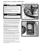
INSTALLATION - ELECTRICAL CONNECTIONS
All wiring must be done in accordance with the National Electric
Code, latest edition, (NFPA No. 70). Canadian electrical code
C22.1 applies in Canada. All internal wiring has been completed
at the factory. Provide electric service from a fused disconnect
switch to the power terminal block in the power junction box
on the unit heater. Wiring must be Type TW insulation for 60°C
(140°F) or better for Models VE50 thru VE250. Use type THW
insulation for 75°C (167°F) for Models VE and PTE 300, 400
500. Appliance wiring diagrams are located inside the power
junction box cover.
Make connections strictly in accordance with wiring
diagram furnished with unit. Any wiring differing from this
diagram may be hazardous to persons and property.
Any damage to, or failure of Modine units caused by
incorrect wiring of the units is not covered by Modine’s
standard warranty.
The location of a remote thermostat should be determined
by the heating requirements and mounted on an inside wall
approximately 5 feet above the floor. It must not be located
where it would be affected by direct heat from the unit or other
sources, or drafts from frequently opened doors or windows.
See instructions packed with thermostat. The unit may also be
controlled by a remote, manual on-off switch.
Control wiring should be No. 14 AWG (American Wire Gauge.)
Total line amperes in Table 8.1 includes fan motor and element
current. (FLA). Refer to Table 6.3 for motor current draw.
All 480 volt, three-phase units have built-in transformers and
fuses to stepdown voltage and protect motor and control circuit.
Fuse blocks with fuses are factory-installed on all 480 volt,
3-phase units to protect motor control and motor transformer.
All contactor coils are rated at 208-240 volts.
Models VE and PTE 300,400, 500 with 480 volt, 3-phase power
supply are wired for two-stage control as standard equipment
and have two contactors.
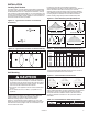
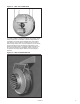
Figure 7.1 - Power junction box, Models VE50 thru VE250
POWER
TERMINAL
BLOCK
CONTROL
TERMINAL BLOCK
GROUND
LUG
CONTACTOR
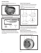
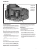
Figure 7.2 - Transformer and Fuse Box
TRANSFORMER
FUSE
BLOCK
W/FUSES
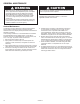
WARNING
1. Disconnect power supply before making wiring
connections to prevent electrical shock and equipment
damage.
2. All appliances must be wired strictly in accordance with
wiring diagram furnished with the appliance. Any wiring
different from the wiring diagram could result in a hazard
to persons and property.
3. Ensure that the supply voltage to the appliance, as
indicated on the serial plate, is not 5% greater than rated
voltage.
CAUTION
1. Ensure that the supply voltage to the appliance, as
indicated on the serial plate, is not 5% less than the rated
voltage.
Wiring
7