
Product Brochure


C
US
3
6-107.14
DO NOT LOCATE ANY GAS-FIRED UNIT IN AREAS WITH CHLORINATED,
HALOGENATED, OR ACIDIC VAPORS IN ATMOSPHERE.
Request Catalog 6-175 For Complete Technical Information and Specifications.
DO NOT LOCATE ANY GAS-FIRED UNIT IN AREAS WITH CHLORINATED,
HALOGENATED, OR ACIDIC VAPORS IN ATMOSPHERE.
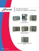
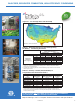
GAS-FIRED, SEPARATED COMBUSTION, PROPELLER
• 100% Outside Air for Combustion • Sealed Compartment Protects Combination Gas Control, Ignition Control,
Manifold and Burner • Horizontal or Vertical Concentric Venting • 80% Thermal Effi ciency • Direct Spark Ignition
• 100% Shut-Off with Continuous Retry • Certifi ed for Commercial or Residential Applications
MODEL HDS
MODEL PTS
The separated combustion models HDS and PTS draw 100% of their combustion air from
outside to ensure that the unit will always have plenty of fresh, clean air to breathe. This
fresh-air supply reduces common concerns about maintenance, performance, and
durability in dusty, dirty, or humid applications. In addition, by drawing the combustion
air from the outside, the overall heating ef ciency is increased. In short, the separated
combustion units give you the added advantages of:
• 80% thermal efficiency for fuel savings.
• A sealed compartment protects the combination gas valve, ignition control, manifold, and
burner from the environment.
• External gas connections.
• Uses natural or propane gas ( eld convertible from natural to propane gas).
• Certi ed for residential (30-125MBH), commercial and industrial use (30-400MBH).
• Lightweight, easily installs 1" from ceiling with only two angle brackets (standard on 30-75,
accessory for 100-125).
• Install quickly and easily with knockouts for quick access to gas and electricity.
• Standard power exhaust simpli es side-wall or roof venting with small-diameter vent pipe.
• Horizontal or vertical two-pipe or concentric venting options.
• Permanently-lubricated motor for trouble-free dependability.
• Full 10-year warranty on heat exchanger.
• Available in both propeller fan and centrifugal blower con gurations.
For blower model data, see page 6.
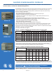
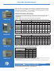
Table 3.1 - Propeller Unit Model HDS and PTS General Performance Data
Model HDS Sizes Model PTS Sizes
30 45 60 75 100 125 150 175 200 250 300 350 400
Btu/Hr Input ➀
30,000 45,000 60,000 75,000 100,000 125,000 150,000 175,000 200,000 250,000 300,000 350,000 400,000
Btu/Hr Ouput ➀
24,000 36,000 48,000 60,000 80,000 100,000 120,000 140,000 160,000 200,000 240,000 280,000 320,000
Entering Airflow (CFM)
@ 70°F
505 720 990 1160 1490 1980 2140 2725 2870 3995 4545 5280 5995
Air Temp. Rise (°F) 44 46 45 48 50 47 53 48 52 47 50 50 51
Max. Mounting
Height (Ft.) ➁
10 10 12 14 12 16 15 14 15 18 19 18 21
Heat Throw (Ft.) @
Max Mtg Ht ➁
25 27 36 38 42 56 51 50 53 62 69 65 74