
Install Instructions


IHR Series Manual
22
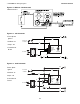
4.0 Maintenance • Heater Assembly Components
Heater Assembly Components
NOTE: Replacement burners are called “rayheads” with rod inserts. Ceramic grids are not sold separately.
Path of
exhaust
Pilot or Electrode
Assembly
Gas
Orifice
Figure 4.1 • Heater Assembly Components
(side view)
Figure 4.3 • Spark Electrode Side View
(Direct Spark) Figure 4.4 • Pilot Assembly Side View
(Millivolt)
Ceramic Tile
Pilot Burner
Pilot Orifice
Pilot Shield
Powerpile
Figure 4.2 • Heater Assembly Components
(rear view of Direct Spark)
Side Frame
Rayhead Assembly
with Ceramics
Heat Shield
Brass
Union
Reflector Shield
Rods
Manifold
End Frame
Assembly
Manifold
Pressure
Tap
Cross-over
Bracket
High
Voltage
Wire
Low
Voltage
Wire
Circuit Board
(Housed inside
Junction Box)
Gas
Valve
Side Frame
Rods
Set gap to 1/8” - 3/16”
Electrode Bracket
Proper installation results
in 1/8” clearance from
face of ceramic
Electrode
Ceramic
Tile
Side View