
HER Installation and Service Manual


2-525.6
44
INSTALLATION
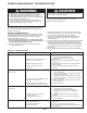
WARNING
1. Disconnect power supply before making wiring connections
to prevent electrical shock and equipment damage.
2. All appliances must be wired strictly in accordance with
wiring diagram furnished with the appliance. Any wiring
different from the wiring diagram could result in a hazard
to persons and property.
3. Ensure that the supply voltage to the appliance, as indicated
on the serial plate, is not 5% greater than rated voltage.
Electrical Connections
CAUTION
1. Ensure that the supply voltage to the appliance, as indicated
on the serial plate, is not 5% less than the rated voltage.
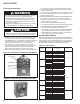
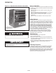
Figure 4.1 - Control Panel Viewed from Unit Bottom
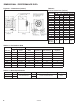
Figure 4.2 - Rear View with Unit Mounted T-stat
Table 4.1 - Wiring Data
POWER TERMINAL
BLOCK
CONTROL TERMINAL
BLOCK
ELEMENT
CONNECTORS
CONTACTOR
1. Installation of wiring must conform with local building codes,
or in the absence of local codes, with the National Electric
Code ANSI/NFPA 70 - Latest Edition. Unit must be electrically
grounded in conformance to this code. In Canada, wiring
must comply with CSA C22.1, Part 1, Electrical Code.
2. Two copies of the unit wiring diagram are provided with
each unit. One is located in the bottom control compartment
access panel and the other is supplied in the literature
packet. Refer to this diagram for all wiring connections.
3. Make sure all multi-voltage components (motors, transformers,
etc.) are wired in accordance with the power supply voltage.
4. The power supply to the unit must be protected with a fused
or circuit breaker switch.
5. The power supply must be within 5% of the voltage rating and
each phase must be balanced within 2% of each other. If not,
advise the utility company.
6. External electrical service connections that must be installed include:
a. Supply power connection (208, 240, 480 or 600 volts).
b. Connection of thermostats, or any other accessory control
devices that may be supplied.
7. Additional electrical wiring details are as follows:
1. Control wiring should be No. 14 AWG (American Wire Gauge).
2. All 480/600 volt units have built-in transformers and fuses.
3. All contactor coils are rated at 208-240 volts.
4. Fuse blocks with fuses are factory installed on all 480/600
volt three-phase units to protect motor and transformer.
5. Models HER200 and HER250 with 208- or 240-volt three
phase power supply have two contactors.
Summer/Winter Switch
A summer/winter toggle switch kit is available for field installation. In
the winter position the thermostat will cycle the fan on and off with the
heating elements. In the summer position the fan runs continuously
while the heating elements are controlled by the thermostat. Refer to
separate bulletin included in the kit for installation and wiring.
Model Size Power Code Supply Voltage
Control Box Volume
(cm
3
)
30
11 208V/1ph
12,076.84
12 240V/1ph
31 208V/3ph
32 240V/3ph
33 480V/3ph
34 600V3ph
50
11 208V/1ph
12 240V/1ph
31 208V/3ph
32 240V/3ph
33 480V/3ph
34 600V/3ph
75
11 208V/1ph
17,563.11
12 240V/1ph
31 208V/3ph
32 240V/3ph
33 480V/3ph
34 600V/3ph
100
11 208V/1ph
12 240V/1ph
31 208V/3ph
32 240V/3ph
33 480V/3ph
34 600V/3ph
125
31 208V/3ph
32 240V/3ph
33 480V/3ph
34 600V3/ph
150
31 208V/3ph
32 240V/3ph
33 480V/3ph
34 600V/3ph
200
31 208V/3ph
30,331.21
32 240V/3ph
33 480V/3ph
34 600V3ph
250
31 208V/3ph
32 240V/3ph
33 480V/3ph
34 600V/3ph