
HER Installation and Service Manual
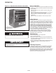


2-525.6
3
UNIT LOCATION
UNIT MOUNTING
In locating units, consider general space-heating requirements
of the area. Unit heaters should be located so they discharge
air nearly parallel to exposed walls. Arrange units so they do
not blow directly at occupants. Interference of air streams by
columns, beams, partitions, or other obstructions should be
avoided as much as possible.
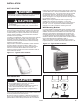
In multiple unit installations, arrange units so that each supports
the air stream of the next unit, thus creating circulatory air
movement in the area. See Figure 3.1. A large portion of the
heated air should be directed toward the side of the building
exposed to prevailing winds.
Height at which unit heaters are installed is critical. Maximum
mounting heights for all units are listed in Table 6.2. The
maximum mounting height for any unit is that height above
which the unit will not deliver heated air to the floor. The
maximum mounting heights must not be exceeded in order to
assure maximum comfort.
Figure 3.1 - Typical Unit Locations
Figure 3.1 - Typical Unit Locations
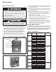
Figure 3.3 - Ceiling Suspension Methods
3
INSTALLATION
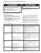
DANGER
Appliances must not be installed where they may be exposed
to a potentially explosive or flammable atmosphere.
CAUTION
1. Do not install appliance closer than 12 inches to
combustible materials in any direction.
2. The bottom of the appliance for HER 30-50: must be at
least - 6ft USA & 8ft Canada, HER 75-250: - 8ft..
3. Do not attach duct work, air filters, or polytubes to any
appliance.
CAUTION
1. Be sure no obstructions block air intake or discharge of
the appliance.
2. Do not install appliance outdoor, wet, or moist locations.
It is recommended that adequate service access in excess of 18
inches be provided for the motor and fan.
Be sure the means of suspension is adequate to support the
weight of the unit (see note). Clearances to combustibles as
specified above must be strictly maintained. Do not install unit
heater above the maximum mounting height shown in Table 6.2
or below HER 30-50: - 6ft USA, 8ft Canada & HER 75-250: - 8ft.
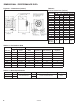
Two tapped holes (3/8" - 16) in the top of the unit are provided
for unit heater suspension. Suspension can be made with
threaded rods, pipes, or ceiling hanger brackets furnished by
others. See Figure 6.1 for hanger hole locations and Figure 3.3
for suspension methods.
NOTE: A pipe hanger adapter kit, shown in Figure 3.3 is
available as an accessory from Modine, or can be self-
fabricated. Kit consists of two drilled 3/4" I.P.S. pipe caps and
two 3/8" - 16 x 1-3/4" capscrews to facilitate threaded-pipe
suspension. One kit is required for mounting each unit.
Wall-Mounting Bracket
For easier installation of Model HER electric unit heaters, where
ceiling suspension is not feasible, a wall-mounting bracket kit is
available. The bracket saves installation time, has a built-in wall
clearance, and provides an inexpensive and convenient wall
mounting method. The one-point suspension, shown in Figure
3.2, permits swiveling the unit 90 degrees horizontally for most
effective air direction. Refer to separate bulletin furnished with the
kit for bracket assembly and installation. Refer to
Table 6.2 for maximum mounting height. Minimum mounting
height is HER 30-50: - 6ft USA, 8ft Canada & HER 75-250: - 8ft.