
Installation and Service Manual


3
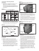
Figure 3.1
V/VN, WVC/WVN Model Bracket Mounted Transformer
Figure 3.2
PT/PTN, WPC/WPN Bracket Mounted Transformer
For V/VN, WVC/WVN Models Direct Mount:
1) Insert the foam pad between the integral top transformer
mounting bracket and the top of the casing for V/VN, WVC/
WVN models. The top for V/VN, WVC/WVN is identified as
the casing side opposite the side of leaving airflow with the
fan guard.
2) Use two #10-24x½” self-drilling screws to fasten the
transformer to the unit heater casing panel, using the
casing panel screw locating guide holes.
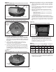
3) Insert the foam pad between the back of the transformer
j-box and the unit heater casing panel as shown in Figure
3.3. From within the transformer j-box, use one #10-24x½”
self-drilling screw to fasten the transformer to the unit
heater casing panel, using the casing panel screw locating
guide hole.
Figure 3.3
V/VN, WVC/WVN Model Direct Mounted Transformer
Wiring the Transformer Accessory to the Unit Heater
1) Install the wiring harness (conduit, connectors and wires)
between the transformer junction box and the unit heater
junction box.
2) Connect the wiring harness wiring ends in the unit heater
junction box as shown in the unit heater wire diagram for
115V single-phase power.
3) Within the transformer junction box, interconnect the
transformer secondary leads and wiring harness wiring
ends as follows:
• Transformer wires X1 and X3 are connected to the
white harness wire.
• Transformer wires X2 and X4 are connected to the
black harness wire.
4) Connect the incoming electrical power feed line to the
transformer junction box with an appropriate box connector.
5) Within the transformer junction box, connect the incoming
electrical power feed circuit ground wire to the transformer
grounding lug. See Figure 3.4 for location of the ground
lug.
Figure 3.4
Transformer Accessory Ground Lug Location
6) Within the transformer junction box, interconnect the
transformer primary wires (labeled H1, H2, etc.) and
connect the incoming electrical power feed wires as
indicated in Table 3.1 for the voltage and transformer
manufacturer supplied. The connection charts are also
provided on the transformer casing.
Table 3.1
Transformer Accessory Primary Wiring Connections
7) Turn the power supply on to unit. Verify the voltage from
the transformer to unit. Also verify that the unit operates as
detailed in the unit Installation and Service Manual, 1-550
or AIR1-550 latest edition.
Primary Voltage 208 240 480 600
Supplier Hevi-Duty Jefferson All All Hevi-Duty Jefferson
Size 1.0KVA All All All All All
Interconnect H2 to H3 None H1 to H3 H2 to H3 None Required
Primary Required H2 to H4
Connect Primary H1 & H4 H1 & H2 H1 & H4 H1 & H4 H1 & H2 H1 & H2
Lines To
FOAM
PAD
(1) SELF-DRILLING
SCREW
NUTS ON
PROVIDED
CAP
SCREWS
1-556.2
FOAM
PAD
NUT ON
EXISTING
THREADED
STUD
NUT ON
EXISTING
THREADED
STUD
(2) SELF-DRILLING
SCREWS
FOAM
PAD
(2) SELF-DRILLING
SCREWS
(1) SELF-DRILLING
SCREW
MOUNTING
HOLE
GROUND LUG
(2) SELF-DRILLING SCREWS
WITH FOAM PAD (NOT SHOWN)
FOAM
PAD