
Data Sheet

CoreDeviceInterfaceSpecifications ModernRoboticsInc
Page7of10
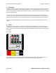
ModernRoboticsCoreDeviceInterface
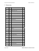
TheD7–D0inputstatefieldisabytecontainingthecurrentlogiclevelspresentontheD7–D0channel
pins.Ifaparticularpinisinoutputmode,thecurrentoutputstatewillbereported.
TheD7–D0I/Ocontrolfieldisabytecontainingtherequired
I/OstateoftheD7–D0channelpins.Ifa
particularbitissettoone,thecorrespondingchannelpinwillbeinoutputmode,elseitwillbeininput
mode.
TheD7–D0outputsetfieldisabytecontainingtherequiredI/Ooutputofthe
D7–D0channelpins.If
thecorrespondingD7–D0I/Ocontrolfieldbitissettoone,thechannel pinwillbeinoutputmodeand
willreflectthevalueofthecorrespondingD7–D0outputsetfieldbit.
4.4 AnalogOutput
TheAnalogOutputportsare2pinconnectorsproviding signalandground.Therearethreevaluesfor
eachofthetwoAnalogOutputportsthatcontrolthemodeand outputvoltageofeachport.Theseare
outputmode,outputvoltageandoutputfrequency.
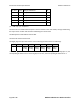
Theoutputmodecanbe
settooneofthefollowing;
Mode Channel operation Voltage range
0 Voltage output -4v – +4v
1 Sine wave output 0 – ±4v (8v p-p)
2 Square wave output 0 – ±4v (8v p-p)
3 Triangle wave output 0 – ±4v (8v p-p)
Theoutputvoltagefieldwillsetthechanneloutputvoltageintherange‐4to+4voltsinVoltageoutput
mode(mode0)basedonthevaluethatcanrangefrom‐1023to1023.Ifthemodeisinwaveformmode
(1,2or3),thisfieldcontrolsthepeaktopeak
voltageintherange0–8voltsbasedonthe valuebeing0