Modern Robotics, Inc Core Device Interface Module Version 1.
Core Device Interface Specifications Modern Robotics Inc 1 Contents 2 Document Control................................................................................................................................. 3 3 Overview ............................................................................................................................................... 4 4 Ports ..........................................................................................................................
Core Device Interface Specifications Modern Robotics Inc 2 Document Control Revision History Version Date Description By 1.0 November 5, 2014 Initial document Modern Robotics 1.1 April 20, 2015 Minor updates Modern Robotics © Modern Robotics, Inc 2014, 2015 This document is published by Modern Robotics, Inc. No part of this document may be copied, published in print or shared online or otherwise publically released without the express written consent of Modern Robotics, Inc.
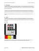
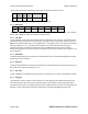
Core Device Interface Specifications Modern Robotics Inc 3 Overview The Modern Robotics Core Interface Device has 26 ports for connecting sensors and devices that can be read from a host via USB and. The Core Device Interface, or CDI, provides 8 digital I/O ports, 8 analog inputs, 2 analog outputs, 2 PWM outputs and 6 I2C bus ports. The CDI is powered from the 5v available from the USB connection. To access ports on the CDI, requests are written to the memory map and results are read from the memory map.
Core Device Interface Specifications Modern Robotics Inc The I2C read functionality is defined by a data structure used to initialize I2C reads. Mode I2C addr Mem addr Mem len B0 – B26 Flag byte byte byte byte bytes byte The Mode byte controls the overall functionality of the channel. 4.1.1 Mode byte D7 D6 D5 D4 D3 D2 D1 D0 R/W - - - - - - - The R/W bit is used to control what kind of I2C transaction to perform. If R/W bit is set, the transaction will be read.
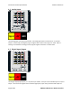
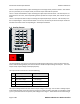
Core Device Interface Specifications Modern Robotics Inc 4.2 Analog Input The 8 Analog Input ports have 3 pin headers. The analog signal values can be from 0v – 5v and the output is a 10 bit A/D, providing the program register with a value in the range of 0 – 1023. Note: If nothing is connected to an analog port the program register will contain a random value. 4.3 Digital Input/Output The 8 Digital Input/Output ports, D7 – D0, have 3 pin headers. Each port can be individually set as input or output.
Core Device Interface Specifications Modern Robotics Inc The D7 – D0 input state field is a byte containing the current logic levels present on the D7 – D0 channel pins. If a particular pin is in output mode, the current output state will be reported. The D7 – D0 I/O control field is a byte containing the required I/O state of the D7 – D0 channel pins. If a particular bit is set to one, the corresponding channel pin will be in output mode, else it will be in input mode.
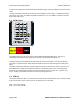
Core Device Interface Specifications Modern Robotics Inc to 1023. If the voltage value is set outside of the allowable range, it will be modified to force the value in range. The output frequency field will set the channel output frequency in the range 1 – 5,000Hz based on the value being in the range 1 to 5,000 if the Mode is waveform (1, 2 or 3). If Mode 0 is selected, this field will be over‐written to 0. 4.5 PWM Output The PWM Output ports, P0 and P1 output a Pulse Width Modulated (PWM) signal.
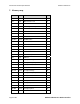
Core Device Interface Specifications Modern Robotics Inc 5 Memory map. Address Type Contents R/W 00H byte Device version number r/o 01H byte Manufacturer code r/o 02H byte Device id.
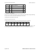
Core Device Interface Specifications Modern Robotics Inc 30 – 4FH struct I2C port I2C0 buffer r/w 50 – 6FH struct I2C port I2C1 buffer r/w 70 – 8FH struct I2C port I2C2 buffer r/w 90 – AFH struct I2C port I2C3 buffer r/w B0 – CFH struct I2C port I2C4 buffer r/w D0 – EFH struct I2C port I2C5 buffer r/w r/o – read only.