
Data Sheet
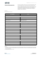

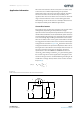

Table Of Contents
- General Description
- Pin Assignment
- Environmental Specifications
- Electrical Characteristics
- Detailed Description
- Application Information
- Mechanical Information
- Soldering Information
- Ordering & Contact Information
- RoHS Compliant & ams Green Statement
- Copyrights & Disclaimer
- Document Status
- Revision Information
- Content Guide
ams Datasheet Page 9
[v1-01] 2015-Oct-12 Document Feedback
AS-MLV-P2 − Application Information
A constant current source can also be used to read-out the
sensitive layer. In this case the electrical power dissipated in the
sensitive layer must be limited and must not exceed 1mW for
all values of R
S
.
Heater Control
To solve the application the sensor needs a certain temperature,
the operation point. This temperature correlates with the
heater resistance of the sensor module. The heater resistance
and its TCR varies with production and the sensor temperature
should be adjusted by applying a calibration step up front. In
this calibration step the characteristic of the correlation of
temperature and heater power is used. For iAQ applications the
dependency for the operation temperature of ~300°C is 34mW
@ 23°C ± 2°C. The measured heater resistance value with this
applied conditions is the set-point which will be important for
the further operation.
Variation of ambient temperature may have an influence in the
sensor temperature and its heater resistance. The chosen circuit
shall be adjustable and should keep the heater resistance
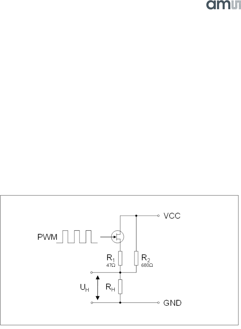
constant at the desired set-point. This can be solved by a basic
PWM circuit shown in Figure 10.
Figure 10:
Basic PWM Circuit for Heater Control
Basic PWM Circuit for Heater Control: A typically heater driver circuit, R1 is the current limit resistor, R2 is
needed as a bypass resistor