
Data Sheet
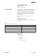
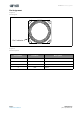
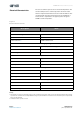

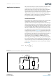

Table Of Contents
- General Description
- Pin Assignment
- Environmental Specifications
- Electrical Characteristics
- Detailed Description
- Application Information
- Mechanical Information
- Soldering Information
- Ordering & Contact Information
- RoHS Compliant & ams Green Statement
- Copyrights & Disclaimer
- Document Status
- Revision Information
- Content Guide
ams Datasheet Page 7
[v1-01] 2015-Oct-12 Document Feedback
AS-MLV-P2 − Application Information
Due to the characteristics of the sensor, there are some issues
to be taken care of while implementing. The operation
temperature of the sensor has to be kept constant; therefore
the circuit on heater site shall have the possibility to be
regulated. The critical issue of the sensor resistance is the wide
range of values which has to be covered during operation.
All following circuits are meant to be examples which have to
be adapted carefully to the different applications.
Sensor Resistance
The sensitive layer can change its resistance over several orders
of magnitude, depending on the production and gas
exposition. The electrical power dissipated in the sensitive layer
must be limited and must not exceed 2mA. This power shall also
avoid performing high changes over short time. Because of this
issue a measuring range shifting realized with series resistors
will have an effect to the sensor signal and should be avoided.
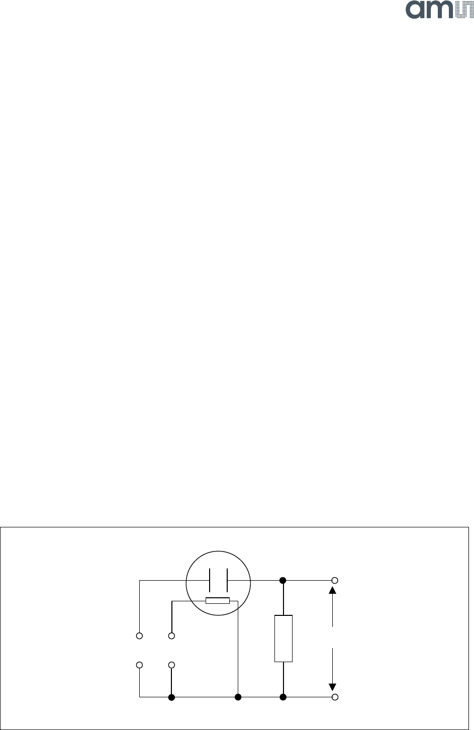
As a suggestion we measure the sensor resistance with a simple
voltage divider as shown in Figure 8. V
H
determines the heater
voltage and therefore the operation temperature of the sensor.
This regulation is described in a later chapter. Here we focus on
the sensor resistance measuring. To meet the described
specification a value of 10kOhm or 100kOhm for the load
resistor (R
L
) and a Voltage of 5V for V
S
is a good starting point
for a broad range of the sensor applications. A high precision
noise free voltage source is recommended for generating V
S
. R
S
and R
L
form a voltage divider, which can be used to calculate
R
S
(see EQ 1).
Figure 8:
A Basic Measurement Circuit for the Sensor Resistance
Application Information
(EQ1)
R
S
R
L
V
S
V
out
------------
1–
=
V
out
V
s
R
L
R
S
V
H
1
3
2
4