
Data Sheet
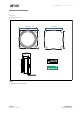
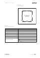
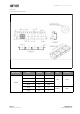

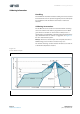
Table Of Contents
- General Description
- Pin Assignment
- Environmental Specifications
- Electrical Characteristics
- Detailed Description
- Application Information
- Mechanical Information
- Soldering Information
- Ordering & Contact Information
- RoHS Compliant & ams Green Statement
- Copyrights & Disclaimer
- Document Status
- Revision Information
- Content Guide

ams Datasheet Page 17
[v1-01] 2015-Oct-12 Document Feedback
AS-MLV-P2 − Mechanical Information
Note(s):
1. All dimensions are in millimeters unless otherwise stated.
2. Unspecified dimension tolerance should be ±0.10mm.
3. Cumulative tolerance of 10 sprocket holes is ±0.20mm.
Perforation
Diameter ΘD0 1.50
mm
+0.10
Diameter ΘD1 1.50 -0.00
Pitch P0 4.00
±0.10
Pitch P2 2.00
Position E 1.75
Distance between
center line
Width F 7.50
Carrier tape
material
Type Echips
Width W 16.00
mm
±0.30
Thickness T 0.50 ±0.05
Requirement/
Notice
1. Camber 250mm. Should be less than 1.00mm by Camber gauge.
2. Must conform to E.I.A. Standard.
Description Items Symbol Value Unit Tolerance