
Data Sheet
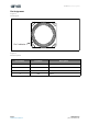

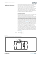

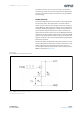
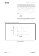
Table Of Contents
- General Description
- Pin Assignment
- Environmental Specifications
- Electrical Characteristics
- Detailed Description
- Application Information
- Mechanical Information
- Soldering Information
- Ordering & Contact Information
- RoHS Compliant & ams Green Statement
- Copyrights & Disclaimer
- Document Status
- Revision Information
- Content Guide
Page 10 ams Datasheet
Document Feedback [v1-01] 2015-Oct-12
AS-MLV-P2 − Application I nfo rmation
To use the example a p-channel MOSFET is mandatory; using
an n-channel will need a change of the overall circuit design. In
this case the Voltage VCC is 5V with a max ripple of 20mV, but
the circuit is also valid for 3.3V. The circuit should be designed
to achieve a PWM of 30-60% depending on heater set-point.
This range gives the security that all specified environmental
temperature ranges can be compensated.
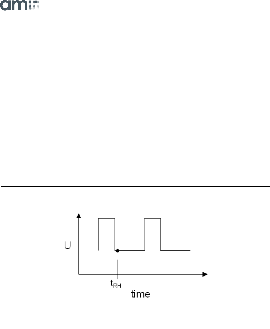
The heater resistance should be measured at the beginning of
the low phase indicated as T
RH
in the drawing Figure 11. The
Voltage drop UH is measured and Rh can be calculated as shown
in EQ 2.
Please note that this circuit are just mend to be an example and
each circuit which can fulfill the conditions and respects the
absolute maximum ratings of the sensor can be used.
Figure 11:
Example of PWM Cycle with Measurement Point
The heater can also be controlled by a DAC controlled circuit
with a voltage divider.
(EQ2)
R
H
U
H
R
2
⋅
VCC U
H
–
---------------------------
=