AS-MLV-P2 Air Quality Sensor General Description The ams AS-MLV-P2 is a MOS (metal oxide semiconductor) based gas sensor component. It was specifically designed for a broad detection of reducing gases such as VOCs (volatile organic compounds) and CO (carbon monoxide) associated with bad air quality. The AS-MLV-P2 sensor component is a MEMS (micro electromechanical system) device using silicon wafer technology. Ordering Information and Content Guide appear at end of datasheet.
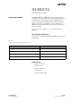
AS-MLV-P2 − Pin Assignment Pin Assignment Figure 2: Pin Diagram Pin 1 Indicator 2 3 1 4 Figure 3: Pin Description Pin Number Pin Name 1 RS1 Sensor electrode 1 2 RH1 Heater 1 3 RS2 Sensor electrode 2 4 RH2 Heater 2 Page 2 Document Feedback Description ams Datasheet [v1-01] 2015-Oct-12
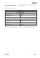
AS-MLV-P2 − Environmental Specifications The sensor element characteristics are valid under the following environmental conditions: Environmental Specifications Figure 4: Environmental Operating Conditions Description Value Ambient Operating Range Temperature range 0°C to 50°C Humidity range (relative humidity, non-condensing) 5% to 95% Ambient Storage Range Storage temperature range -40°C to 85°C Storage humidity range (relative humidity, non-condensing) 5% to 95% Air Flow Experienced air velo
AS-MLV-P2 − Electrical Characteristics Electrical Characteristics The sensor elements operate at an elevated temperature. The elevated temperature is realized by means of the Pt heater which is implemented within the silicon nitride membrane. The recommended operating temperature for the AS-MLV-P2 is 300°C, which is equivalent to an applied power of approx. 34mW at room temperature.
AS-MLV-P2 − Detailed Description AS-MLV-P2 heater and inter-digital electrode structures use Platinum and are implemented in an approximately one micrometer-thin silicon nitride membrane to achieve ultimate stability and lowest possible power consumption. A highly sensitive and long-term stable polycrystalline tin dioxide-based sensitive material is deposited on the inter-digital electrodes. At an elevated operation temperature of approx.
AS-MLV-P2 − Detailed Description Cross Sensitivities Due to the basic operation principle of MOS gas sensors, the AS-MLV-P2 sensor component does have a cross sensitivity to humidity changes. This effect provides additional information and widens the application range for the sensor. This feature especially supports applications in environments where the detection of significant humidity changes is supporting the functionality, such as bathroom and kitchen environments.
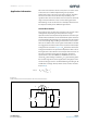
AS-MLV-P2 − Application Information Due to the characteristics of the sensor, there are some issues to be taken care of while implementing. The operation temperature of the sensor has to be kept constant; therefore the circuit on heater site shall have the possibility to be regulated. The critical issue of the sensor resistance is the wide range of values which has to be covered during operation.
AS-MLV-P2 − Application Information The resolution of the measurement of R S is recommended to be better or equal to 1% of the actual reading. This allows making use of the full performance of the sensor. The requirements for the A/D conversion of the output voltage Vout is described in the following section.
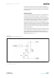
AS-MLV-P2 − Application Information A constant current source can also be used to read-out the sensitive layer. In this case the electrical power dissipated in the sensitive layer must be limited and must not exceed 1mW for all values of R S. Heater Control To solve the application the sensor needs a certain temperature, the operation point. This temperature correlates with the heater resistance of the sensor module.
AS-MLV-P2 − Application Information To use the example a p-channel MOSFET is mandatory; using an n-channel will need a change of the overall circuit design. In this case the Voltage VCC is 5V with a max ripple of 20mV, but the circuit is also valid for 3.3V. The circuit should be designed to achieve a PWM of 30-60% depending on heater set-point. This range gives the security that all specified environmental temperature ranges can be compensated.
AS-MLV-P2 − Application Information Heater Calibration As mentioned in the previous chapter the each sensor has its own set-point at the operation temperature. This set-point can be determined by a previous calibration step. This means that the AS-MLV-P2 is started at room temperature (23°C ± 3°C) and powered with 34mW. With these conditions the heater resistance is measured and stored into the EEPROM.
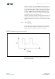
AS-MLV-P2 − Application Information A characteristic example is shown in Figure 13. This behavior is caused due to manufacturing issues and is mandatory. After once following this issue it will never appear again. During the burn in phase the resistance range can be exceeded considerably.
AS-MLV-P2 − Application Information Run-In Each time after powering the sensor, the baseline of the sensitive layer performs a small run in phase. The curve is characterized with a steady increasing resistance. The length of this phase is depending on the sensors history. The longer the sensor was unpowered the longer the run in phase will take. The standard duration is approx. 3-5 minutes.
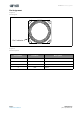
AS-MLV-P2 − Mechanical Information Mechanical Information Figure 15: Module Dimensions 9.1 ±0.30 8.1 ±0.30 3 1 4 8.1 ±0.30 9.1 ±0.30 2 4.53 ±0.20 2.650 Ø7 RoHS Green 1.55 ±0.10 Note(s): 1. All Dimensions are in millimeters.
AS-MLV-P2 − Mechanical Information Figure 16: Module Markings AS-MLV-P2 SNYYxxxxxxx Figure 17: Module and Marking Elements Item Description PCB Material FR4 with gold surface (7μm Ni / 3μm Au) Connector Edge connector Marking PIN1 White mark Label Laser mark AS-MLV-P2 Product name (first row) AS-MLV-P2 SNYYxxxxxxx Serial number (second row) YY → two digits production year xxxxxxx → 7 digits running number ams Datasheet [v1-01] 2015-Oct-12 Page 15 Document Feedback
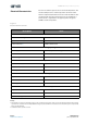
AS-MLV-P2 − Mechanical Information Figure 18: Tape and Reel Information Description Items Symbol Value Length Ao 9.70 Width Bo 9.70 Depth Ko 5.00 Pitch P1 12.00 Angle θ1 3 Angle θ2 3 Unit Tolerance mm ±0.10 Degree Max.
AS-MLV-P2 − Mechanical Information Description Perforation Distance between center line Items Symbol Value Diameter ΘD0 1.50 +0.10 Diameter ΘD1 1.50 -0.00 Pitch P0 4.00 Pitch P2 2.00 Position E 1.75 Width F 7.50 Type Carrier tape material Width Tolerance mm ±0.10 Echips W 16.00 ±0.30 mm Thickness Requirement/ Notice Unit T 0.50 ±0.05 1. Camber 250mm. Should be less than 1.00mm by Camber gauge. 2. Must conform to E.I.A. Standard. Note(s): 1.
AS-MLV-P2 − Soldering Information Soldering Information Handling The AS-MLV-P2 should be handled carefully, shear stress should be avoided. The sensor is protected against particles and liquids by a membrane. This membrane shall not be removed or touched. Soldering Instructions The AS-MLV-P2 can be soldered in standard reflow soldering ovens. The reflow oven shall be purged with clean air. Other gases must be avoided.
AS-MLV-P2 − Ordering & Contact Information Ordering & Contact Information Figure 20: Ordering Information Ordering Code Marking Delivery Form Delivery Quantity AS-MLV-P2 AS-MLV-P2 Tape & Reel 900 Buy our products or get free samples online at: www.ams.com/ICdirect Technical Support is available at: www.ams.com/Technical-Support Provide feedback about this document at: www.ams.com/Document-Feedback For further information and requests, e-mail us at: ams_sales@ams.
AS-MLV-P2 − RoHS Compliant & ams Green Statement RoHS Compliant & ams Green Statement RoHS: The term RoHS compliant means that ams AG products fully comply with current RoHS directives. Our semiconductor products do not contain any chemicals for all 6 substance categories, including the requirement that lead not exceed 0.1% by weight in homogeneous materials. Where designed to be soldered at high temperatures, RoHS compliant products are suitable for use in specified lead-free processes.
AS-MLV-P2 − Copyrights & Disclaimer Copyrights & Disclaimer Copyright ams AG, Tobelbader Strasse 30, 8141 Unterpremstaetten, Austria-Europe. Trademarks Registered. All rights reserved. The material herein may not be reproduced, adapted, merged, translated, stored, or used without the prior written consent of the copyright owner. Devices sold by ams AG are covered by the warranty and patent indemnification provisions appearing in its General Terms of Trade.
AS-MLV-P2 − Document Status Document Status Document Status Product Preview Preliminary Datasheet Datasheet Datasheet (discontinued) Page 22 Document Feedback Product Status Definition Pre-Development Information in this datasheet is based on product ideas in the planning phase of development.
AS-MLV-P2 − Revision Information Revision Information Changes from 1-00 (2015-Jul-10) to current revision 1-01 (2015-Oct-12) Page Updated Figure 3 2 Updated EQ1 7 Updated Figure 8 7 Note(s): 1. Page and figure numbers for the previous version may differ from page and figure numbers in the current revision. 2. Correction of typographical errors is not explicitly mentioned.
AS-MLV-P2 − Content Guide Content Guide Page 24 Document Feedback 1 1 1 General Description Key Benefits & Features Applications 2 3 4 Pin Assignment Environmental Specifications Electrical Characteristics 5 5 6 Detailed Description Sensing Properties Cross Sensitivities 7 7 9 11 11 11 13 Application Information Sensor Resistance Heater Control Heater Calibration General Characteristics Burn-In Behavior Run-In 14 Mechanical Information 18 18 18 Soldering Information Handling Soldering Instruct