
Installation Sheet

2Modern Forms retains the right to modify the design of our products at any time as part of the company's continuous improvement program.
modernforms.com
Phone (800) 526.2588
Fax (800) 526.2585
Headquarters/Eastern Distribution Center
44 Harbor Park Drive
Port Washington, NY 11050
Central Distribution Center
1600 Distribution Ct
Lithia Springs, GA 30122
Western Distribution Center
1750 Archibald Avenue
Ontario, CA 91760
INSTALLATION INSTRUCTION
257 - LED Wall Sconce
WS-25724, WS-25734, WS-25742
PREPARATION
1. Shut o the power at the circuit breaker and remove existing xture, including the crossbar.
2. Carefully unpack your new xture and lay out all the parts on a clear area. Be careful not to lose any small parts necessary for installation.
CONNECTING THE WIRES (Fig. 1/3)
3. Remove the mounting screws (C1) from the xture.
4. Drill holes in the wall aligned with the key holes located in mounting plate, insert the plastic anchors (F1).
5. Secure mounting plate to the junction box using junction box screws (B1), fasten it to the wall using wood screw (E1). The side of the
mounting plate marked “GND” must face out.
6. Connect the xture wires with supply wires as shown in Fig. 3, making sure that all wire connectors (A1) are secured. If your outlet box has
a green or bare copper ground wire, connect the xture’s ground wire to it. Otherwise, connect the xture’s ground wire directly to the
mounting plate using the green screw provided. After wires are connected, tuck them carefully inside the junction box.
MOUNTING THE FIXTURES (Fig. 1/2)
7. The back plate location for this xture is adjustable (Fig. 2).
First loosen both adjustable nuts by turning counterclockwise.
Second adjust the back plate to your desired location.
Third, pull and tighten the electrical wire.
Lastly, secure the back plate by turning both adjustabl nuts clockwise.
8. Place the xture onto the mounting plate, secure it with mounting screws (C1).
9. Thread the clear glass on the top of glass holder; thread the etched glass on
the bottom of glass holder. Secure them with Allen screws (D1) using
Allen wrench (G1).
Plastic
Anchor
Junction
Box
Mounting Plate
Adjustable Nut
Adjustable Nut
Back Plate Dimensions
Fixture
Wire
Clear Glass
(RPL-GLA-25724-01)
Etched Glass
(RPL-GLA-25724-02)
Wire
Connector
Allen
Screw
Allen
Wrench
Wood
Screw
Junction
Box Screw
Mounting
Screw
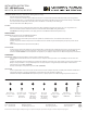
Fixture
F1
A1
E1
B1
D1
G1
C1
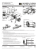
FIG. 1 WS25724
WS25734 WS25742
FIG. 2
Fixture Wires
Black or
Smooth
Fixture Wires
White or
Ribbed
Fixture Wires
Bare wire
(Ground)
House Wires
Black
(Hot)
House Wires
White
(Neutral)
House Wires
Green or Bare Copper
(Ground)
Fig. 3 Wiring
8 1/4"
1 1/2"
1 3/4"
4 1/4"