
Installation & Assembly


2
INSTALLATION INSTRUCTIONS
519-LED Vanities
WS-51920/WS-51927/WS-51937/WS-51920F/WS-51927F/WS-51937F
modernforms.com
Phone (800) 526.2588
Fax (800) 526.2585
Headquarters/Eastern Distribution Center
44 Harbor Park Drive
Port Washington, NY 11050
Central Distribution Center
1600 Distribution Ct
Lithia Springs, GA 30122
Western Distribution Center
1750 Archibald Avenue
Ontario, CA 91760
Modern Forms retains the right to modify the design of our products at any time as part of the company's continuous impro
vement program. Jan 2019
ANUARY, 2017
modernforms.com
Phone (800) 526.2588
Fax (800) 526.2585
Headquarters/Eastern Distribution Center
44 Harbor Park Drive
Port Washington, NY 11050
Central Distribution Center
1600 Distribution Ct
Lithia Springs, GA 30122
Western Distribution Center
1750 Archibald Avenue
Ontario, CA 91760
PREPARATION
1. Shut off the power at the circuit breaker and remove existing fixture, including the crossbar.
2. Carefully unpack your new fixture and lay out all the parts on a clear area. Be careful not to lose any small parts necessary for installation.
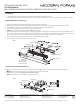
MOUNTING WITHOUT OUTLET BOX (Fig. 1)
3. Remove the mounting screw (B) from the fixture, remove the mounting back plate.
4. Drill two mounting holes in the wall aligned with the key-hole location in the mounting back plate, insert the plastic anchors(C).
5. Drill a small access hole in the wall behind the fixture and pull the house wires through the wall.
6. Secure the mounting back plate to the wall using the wood screw (D).
NOTE
: The side of the mounting plate marked “GND” must face out.
7. Connect the fixture's wires to the supply wires as shown (Fig. 4). Make sure that all wire connectors (A) are secure. If your outlet box
has a
green or bare copper ground wire, connect the fixture’s ground wire to it. Otherwise, connect the fixture’s ground wire directly to the
back
plate using the green screw provided. After wires are connected, tuck them carefully inside the wall or in the fixture.
8. Place the fixture over the mounting back plate and secure it with mounting screw (B) .
9. Secure the glass to the fixture using the mounting screw (B) .
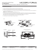
MOUNTING WITH SLIM JUNCTION BOX (Fig. 2)
1. Replace or install new slim junction box (H). Use the two wood screws (D) provided to secure the slim junction box (H) to the wall.
N
OTE: The slim junction box must be recessed about 1/8" into the surface of the wall.
2. Follow steps 3-9 according to "MOUNTING WITHOUT OUTLET BOX."
NOTE: It is not necessary to drill a small access hole in the wall.
FIG. 1
Plastic Anchor
Wood Screw
C
D
Mounting Screw
B
B
Glass
(RPL-GLA-51920
RPL-GLA-51927
RPL-GLA-51937)
B
B
Mounting Screw
Mounting Back Plate
A
FIG. 2
Plastic Anchor
Wood Screw
C
D
Mounting Back Plate
1/8"
3
3
4
"
3
1
2
"
1
1
8
"
Slim Junction Box
Wood Screw
H
~
~
D
Mounting Hole