
Installation Sheet
2
INSTALLATION INSTRUCTIONS
879 - LED PENDANT
PD-87924
Fixture Wires
Black or
Smooth
Fixture Wires
White or
Ribbed
Fixture Wires
Bare wire
(Ground)
House Wires
Black
(Hot)
House Wires
White
(Neutral)
House Wires
Green or Bare Copper
(Ground)
FIG. 2 Wiring
FIG. 1
modernforms.com
Phone (800) 526.2588
Fax (800) 526.2585
Headquarters/Eastern Distribution Center
44 Harbor Park Drive
Port Washington, NY 11050
Central Distribution Center
1600 Distribution Ct
Lithia Springs, GA 30122
Western Distribution Center
1750 Archibald Avenue
Ontario, CA 91760
Modern Forms retains the right to modify the design of our products at any time as part of the company's continuous impro
vement program. Jan 2019
ANUARY, 2017
modernforms.com
Phone (800) 526.2588
Fax (800) 526.2585
Headquarters/Eastern Distribution Center
44 Harbor Park Drive
Port Washington, NY 11050
Central Distribution Center
1600 Distribution Ct
Lithia Springs, GA 30122
Western Distribution Center
1750 Archibald Avenue
Ontario, CA 91760
PREPARATION
1. Shut off the power at the circuit breaker and remove existing fixture,
including the crossbar.
2. Carefully unpack your new fixture and lay out all the parts on a clear
area. Be careful not to lose any small parts necessary for installation.
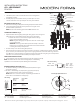
MOUNTING THE FIXTURE (Fig. 1)
3. Remove the mounting screw (B) and mounting back plate from the fixture.
4. Secure the mounting back plate to the junction box using the screws
provided with the junction box.
NOTE: The side of the mounting plate marked “GND” must face out.
CONNECTING THE WIRES (Fig. 2)
5. Adjust the fixture wire length by pushing the cable-gripper on the canopy and
pulling the wire as desired. Make sure the wires are the same length.
a. Retract the wires close to the desired length within the canopy
before securing the fixture into place.
NOTE: Using the cable-gripper to adjust more than 18" of wire length
is not recommended,
WARNING: Shortening cables without professional help or electronic
background is not advisable. Any modifications to the fixture will result
in voiding the warranty of the product.
6. Hook the safety cord to the mounting back plate slot.
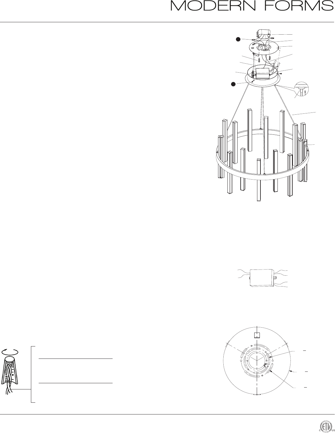
7. Connect the driver's input wires to junction box wires as shown (Fig. 2). Make sure that all wire connectors
(A) are secure. If your outlet box has a green or bare copper ground wire, connect the fixture’s ground wire
to it. Otherwise, connect the fixture’s ground wire directly to the back plate using the green screw provided.
After wires are connected, tuck them carefully inside the junction box.
COMPLETING THE INSTALLATION
8. Secure the fixture to the mounting back plate using the mounting screw (B) .
NOTE:
This fixture features electronic low voltage (ELV) or 0-10V dimming
capabilities. See notes below for specific dimming wires information.
DIMMING WIRING INSTRUCTIONS (Fig. 3)
9. To utilize ELV dimming: use black (hot), white (neutral) and bare copper
ground wire (ground).
10. To utilize 0-10V dimming: use purple (dim+), gray (dim-), black (hot),
white (neutral) and bare copper ground wire (ground).
NOTE: Make sure to connect 0-10V prior to powering up the fixture in
order to allow 0-10V dimmer to work properly.
Purple - Dim+
Gray - Dim-
Black - Hot
White - Neutral
Black - Output -
Red - Output +
FIG.3 Driver Wiring
Mounting Backplate Dimensions
Ø3
1
2
"
Ø2
3
4
"
Ø7
1
2
"
Cord
Safety Cord
Driver input wire
Canopy
A
Wire Connector
Fixture
Mounting Screw
B
Driver (2pcs)
LD-700MA35U-DIM-IS
Push up
Cable-gripper
Junction Box Screw
Junction Box
Ground Wire
Mounting Backplate