
Installation Sheet

2
modernforms.com
Phone (800) 526.2588
Fax (800) 526.2585
Headquarters/Eastern Distribution Center
44 Harbor Park Drive
Port Washington, NY 11050
Central Distribution Center
1600 Distribution Ct
Lithia Springs, GA 30122
Western Distribution Center
1750 Archibald Avenue
Ontario, CA 91760
Modern Forms retains the right to modify the design of our products at any time as part of the company's continuous improvement progr
JANUARY, 2017
modernforms.com
Phone (800) 526.2588
Fax (800) 526.2585
Headquarters/Eastern Distribution Center
44 Harbor Park Drive
Port Washington, NY 11050
Central Distribution Center
1600 Distribution Ct
Lithia Springs, GA 30122
Western Distribution Center
1750 Archibald Avenue
Ontario, CA 91760
am. Nov . 2019
Feb. 2022
INSTALLATION INSTRUCTIONS
PD-82024 / PD-82027 / PD-82042
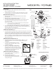
Fig.1
Fig.3
Fig.4
White - Neutral
Black - Hot
Purple - Dim+
Pink or Gray- Dim-
Red - Fixture+
Black - Fixture-
PREPARATION
1.
DIMMING WIRING INFORMATION (Fig. 3)
Fixture Wires
Black or
Smooth
Fixture Wires
White or
Ribbed
Fixture Wires
Bare wire
(Ground)
House Wires
Black
(Hot)
House Wires
White
(Neutral)
House Wires
Green or Bare Copper
(Ground)
Fig. 2 Wiring
Plastic Anchor
Wire Connector
GND Screw
Junction Box Screw
Mounting Screw
Junction Box
Safety Cord
Mounting Plate
Wood Screw
Wire Connector
Fixture’s Wire
Fixture Canopy
Fixture’s Wire
1x 6” Rod
3x12” Rods
Driver
Glass
(RPL-GLA-82024)
Swivel
Base
Turn to down
11. Secure the xture to the mouting plate use
the mounting screw (B).
12. Rotate the glass into the base.
13. For slope ceiling applications, rotate swivel
at the top of the stem to ensure luminaire is
aiming down (Fig.4).
CONNECTING THE WIRES (Fig. 2)
MOUNTING THE FIXTURE (Fig. 1)
3. Remove the mounting screw (B) from the xture, take down the
mounting plate.
4. Drill holes in the wall aligned with the key holes located in the
mounting plate, insert the plastic anchor(E).
5. Secure the mounting plate to the junction box using standard junction
box screws that comes with the junction box. fasten it to the wall
using wood screw(D).
Note: (i) using any other non-original-manufacturer provided junction
box screw may result in safety issue;
(ii) The side of the mounting back plate marked “GND” must face out.
6. Choose the number of the rods suitable for your application. Thread the
xture wire through the rods, swivel and canopy. Connect the xture, rods
and swivel. Make sure all are tightened.
Note:For PD-82042, hook the safety cord to the mounting plate;
7. Connect the xture’s wires with driver’s output wires using wire connectors (B),
Connect the driver’s input wires to junction box wires using wire connectors (A)
as shown in Fig. 2, making sure that all wire connectors are secured. If your
outlet box has a green or bare copper ground wire, connect the xture’s ground
wire to it. Otherwise, connect the xture’s ground wire directly to the mounting
plate using the GND screw provided. After wires are connected, tuck them carefully
inside the junction box.
1. Shut o the power at the circuit breaker and remove existing
xture, including the crossbar.
2. Carefully unpack your new xture and lay out all the parts on a clear
area. Be careful not to lose any small parts necessary for installation.
COMPLETING THE INSTALLATION
(Fig. 1)
8. This xture features electronic low voltage (ELV or TRIAC ) or 0-10V
dimming capabilities. See notes below for specic dimming wires
information.
9. To utilize ELV or TRIAC dimming: use wires
black (hot), white (neutral) and bare copper
ground wire (ground).
10. To utilize 0-10V dimming: use wire purple
(dim+), pink or gray (dim-), black (hot), white
(neutral) and bare copper ground wire (ground).
NOTE: Make sure to connect 0-10V prior to power-
up the xture in order to allow the 0-10V
dimming to function properly.
Ø58”
Ø6w”
Ø3b”
Ø2w”
Mounting Plate Dimensions