
Installation Sheet

2
INSTALLATION INSTRUCTIONS
PD-73032
1-,2
Black or
Smooth
White or
Ribbed
Bare wire
(Ground)
Black
(Hot)
White
(Neutral)
Green or Bare Copper
(Ground)
1!+,3!!+
Phone (800) 526.2588
Fax (800) 526.2585
44 Harbor Park Drive
Port Washington, NY 11050
1600 Distribution Ct
Lithia Springs, GA 30122
1750 Archibald Avenue
Ontario, CA 91760
1. Shut o the power at the circuit breaker and remove existing xture, including the crossbar.
2. Carefully unpack your new xture and lay out all the parts on a clear area. Be careful not to lose any small parts necessary for installation.
.-1451!+,26
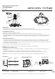
3. Remove the mounting screw (B) from the xture.
4. Drill holes in the wall aligned with the key holes located in the mounting back plate, insert the plastic anchor (C).
5. Secure back plate to the junction box using junction box screws, fasten it to the wall using wood screw (D).The side of the mounting
plate marked “GND” must face out. 6. Adjust the xture wire length by pushing the cable gripper on the canopy and pulling the wire
as desired.
-/51!+,36
7. Connect the driver input wires with junction box wires as shown in Fig.2, making sure that all wire connectors (A) are secured. If your
outlet box has a green or bare copper ground wire, connect the xture’s ground wire to it. Otherwise, connect the xture’s ground
wire directly to the mounting plate using the green screw provided. After wires are connected, tuck them carefully inside the junction box.
8. Hook the safety cords to the back plate.
9. Place the xture over the back plate and secure it with mounting screws (B) .
!+the device is easy to pinch in the process of stretching,Please pay attention to the adjustment.
..--1.51!+,6
1. This xture features electronic low voltage (ELV or TRAIC) or 0-10V dimming capabilities. See notes below for specic dimming wires
information.
2. To utilize ELV or TRAIC dimming: use wires black (hot), white (neutral) and bare copper ground wire (ground).
3. To utilize 0-10V dimming: use wire purple (dim+), gray (dim-), black (hot), white (neutral) and bare copper ground wire (ground).
1
3
8
"
1
3
4
"
7
7
8
"
Ø8
1
8
"
Ø7
1
2
"
Cable-gripper
Push up
Adjust the fixture wire
length by pushing the cable
gripper on the
canopy and pulling the
wires as desired
.
Safety
C
ords
Back Plate
Mounting Screw
B
Plastic Anchor
C
Wood Screw
D
Wire Connector
A
Ground Wire
Junction Box Screw
Fixture
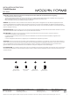
Ø32"-Ø41 5/8”
P
u
l
l
o
u
t
T
o
p
u
s
h
i
n
s
i
d
e
Apply force to the two Fixture points
of the Fixture to enlarge and reduce
Fixture
Rotating points of Fixture
1!+,!7!"
8 $!9"!"
Purple-Dim
Gray-Dim
Red-To Fixture
Black-To Fixture
Black-Hot
White-Neutral
Green-Ground