
Installation Sheet


2
INSTALLATION INSTRUCTIONS
581-LED Pendant
PD-58115
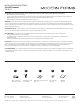
Fig. 1
Fixture Wires
Black or
Smooth
Fixture Wires
White or
Ribbed
Fixture Wires
Bare wire
(Ground)
House Wires
Black
(Hot)
House Wires
White
(Neutral)
House Wires
Green or Bare Copper
(Ground)
Fig. 2 Wiring
modernforms.com
Phone (800) 526.2588
Fax (800) 526.2585
44 Harbor Park Drive
Port Washington, NY 11050
Central Distribution Center
1600 Distribution Ct
Lithia Springs, GA 30122
Western Distribution Center
1750 Archibald Avenue
Ontario, CA 91760
PREPARATION
1. Shut o the power at the circuit breaker and remove existing xture, including the crossbar.
2. Carefully unpack your new xture and lay out all the parts on a clear area. Be careful not to lose any small parts necessary for installation.
MOUNTING THE FIXTURE (Fig. 1)
3. Remove the mounting screw (B) from the mounting back plate.
4. Insert the crystal and diuser into the bracket and thread the wire through the lamp body.
5. Choose number of rods suitable for your application, thread the xture wire through the rods, swivel and canopy. Attach the canopy,
rods, swivel and lamp body. Ensure all are tightened.
Note: (i)Decorative canopy crystal is included as an optional accessory and can be installed at this time with the silicon
gasket (D) as shown in Fig. 4
(ii) Due to limited space within the canopy, shorten the cable as necessary to make the installation easier. Make sure to identify and
label all the wiring properly before any trimming/shortening. (Fig. 5)
6. Secure the mounting plate to the junction box using the screws provided with the junction box.
Note: (i)using any other non-original-manufacturer provided junction box screw may result in safety issue;
(ii) The side of the mounting plate marked “GND” must face out.
CONNECTING THE WIRES (Fig. 2)
7. Connect the driver’s output wires to xture wire as shown in Fig. 5, red to the red, and black to the black, make sure that wire
connectors (A) are secured. Then tuck them inside the canopy.
8. Properly secure the safety cord to the bracket on the mounting back plate to temporarily hang the xture in place and aid installation.
9. Connect the driver’s input wires to junction box wires as shown in Fig. 2, making sure that all wire connectors (A) are secured. If your
outlet box has a green or bare copper ground wire, connect the xture’s ground wire to it. Otherwise, connect the xture’s ground
wire directly to the back plate using the green screw provided
COMPLETING THE INSTALLATION
10. Secure the xture by mounting the canopy to the mounting back plate.Slide the canopy in the direction of the arrow indicated in
Fig 5 until it latches. Secure the xture to the mounting back plate using the mounting screw (B).
11. For slope ceiling application, rotate swivel at the top of the stem to ensure luminaries is aiming down (Fig. 3).
Fig.4
Fig.5 Driver wires
Turn to down
Fig.3
MOUNTING BACK PLATE
5 1/4"
4 5/8"
1 3/4"
1 3/8"
Wire Connector
Junction Box Screw
Mounting Screw
Junction Box
Mounting Back Plate
Safety Cord
Diuser
Crystal
Bracket
Lamp Body
Down Rod
Swivel
Driver
Canopy
B
A
E
Decorative
Canopy Crystal
Swivel
Canopy
Mounting Back Plate
Down Rod
Silicon Gasket
Washer
Nut
Mounting Screw
D
C
Canopy
Driver
Output
Mounting Back Plate
Input
White - Neutral
Black - Hot
Red +
Black -
Center +
Bare -
Mounting Screw