
Installation Sheet


Modern Forms retains the right to modify the design of our products at any time as part of the company's continuous improvement program.
modernforms.com
Phone (800) 526.2588
Fax (800) 526.2585
Headquarters/Eastern Distribution Center
44 Harbor Park Drive
Port Washington, NY 11050
Central Distribution Center
1600 Distribution Ct
Lithia Springs, GA 30122
Western Distribution Center
1750 Archibald Avenue
Ontario, CA 91760
INSTALLATION INSTRUCTION
Cascade - LED Pendant (15 Lights)
PD-41715R
PREPARATION
1. Shut o the power at the circuit breaker and remove
existing xture, including the crossbar.
2. Carefully unpack your new xture and lay out all the
parts on a clear area. Be careful not to lose any small
parts necessary for installation.
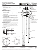
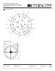
CONNECTING THE WIRES (Fig. 2)
3. Remove the mounting screws (C1) from the xture.
4. Install the mounting back plate to the junction box using
junction box screws (B1)
5. Mark the six wood screw mounting holes on the ceiling,
remove mounting back plate, drill holes and insert the six
plastic anchors (E1)
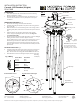
6. Adjust the xture wire length by pushing the cable gripper
on the canopy and pulling the wire as desired.
(see Fig. 3 for recommended length)
7. Connect the driver input wires with supply
wires as shown in Fig. 2, making sure that all
wire connectors (A1) are secured.
If your outlet box has a green or bare copper ground wire,
connect the xture’s ground wire to it. Otherwise, connect the
xture’s ground wire directly to the mounting plate using the
green screw provided. After wires are connected, tuck them
carefully inside the junction box.
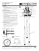
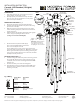
MOUNTING THE FIXTURE (Fig. 1)
8. Install mounting plate back to the junction box using junction
box screws (B1), fasten it to the ceiling using the six wood
screws (D1). The side of the mounting plate marked “GND”
must face out.
9. Hook the two safety cords to the mounting plate
10. Push the xture onto the mounting back plate AND rotate
the xture until it is docked in position, and secure it with
mounting screws (C1).
Fixture Wires
Black or
Smooth
Fixture Wires
White or
Ribbed
Fixture Wires
Bare wire
(Ground)
House Wires
Black
(Hot)
House Wires
White
(Neutral)
House Wires
Green or Bare Copper
(Ground)
Fig. 2 Wiring
FIG. 1
Junction
Box Screw
Plastic
Anchor
Wood
Screw
Mounting
Screw
ROTATE
PUSH
Driver
Cable Gripper
Lamp Body
Crystal Glass
(RPL-GLA-41719)
Safety Cable
Junction Box
Ground Wire
Wire
Connector
Mounting
Back Plate
B1
E1
D1
C1
A1
Cable
gripper
Push up
Instruction: Adjust the xture
wire length by pushing the
cable gripper on the canopy
and pulling the wire as desired.