
Installation Sheet

2
INSTALLATION INSTRUCTIONS
401-Mini Pendant
PD-40106
FIG. 1
Fixture Wires
Black or
Smooth
Fixture Wires
White or
Ribbed
Fixture Wires
Bare wire
(Ground)
House Wires
Black
(Hot)
House Wires
White
(Neutral)
House Wires
Green or Bare Copper
(Ground)
FIG. 2 Wiring
Modern Forms retains the right to modify the design of our products at any time as part of the company's continuous improvement program. Sep. 2020
modernforms.com
Phone (800) 526.2588
Fax (800) 526.2585
Headquarters/Eastern Distribution Center
44 Harbor Park Drive
Port Washington, NY 11050
Central Distribution Center
1600 Distribution Ct
Lithia Springs, GA 30122
Western Distribution Center
1750 Archibald Avenue
Ontario, CA 91760
PREPARATION
1. Shut off the power at the circuit breaker and remove existing xture,
including the crossbar.
2. Carefully unpack your new xture and lay out all the parts on a clear area.
Be careful not to lose any small parts necessary for installation.
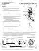
MOUNTING THE FIXTURE (Fig. 1)
3. Loosen the mounting screw (C) from the xture, and remove the mounting
back plate.
4. Secure the mounting back plate to the junction box using standard junction
box screws that comes with the junction box.
Note: (i) Using any other non-original-manufacturer provided junction box
screw may result in safety issue;
(ii) The side of the mounting plate marked “GND” must face out.
5. Adjust the xture wire length by pushing the cable gripper on the canopy
and pulling the wire as desired.
a) Before securing the canopy in place, it is recommended to retract or
extend the wire within the canopy to a desirable length.
b) Due to limited space within the canopy, shorten the cable as necessary
to make the installation easier. Make sure to identify and label all the
wiring properly before any trimming/shortening (Fig. 3).
CONNECTING THE WIRES (Fig. 2 / Fig. 3)
6. Connect the driver’s output wires to center cable as shown in Fig. 3, red to the center, and black to the bare, make sure that wire
connectors (B) are secured. Then tuck them inside the canopy.
7. Connect the driver’s input wires to junction box wires as shown in Fig. 2, make sure that all wire connectors (A) are secured. If your outlet
box has a green or bare copper ground wire, connect the xture’s ground wire to it. Otherwise, connect the xture’s ground wire directly
to the back plate using the screw provided. After wires are connected, tuck them carefully inside the junction box.
8. Secure the xture by mounting the canopy to the ring of the backplate. Turn and rotate the canopy in the direction of the arrow until it
stops. Fasten the canopy to the mounting backplate using the mounting screw (C).
Mounting Backplate Dimensions
Ø4
5
8
"
1
3
8
"
1
3
4
"
Fig.3 Driver Wiring
White - Neutral
Black - Hot
Red +
Black -
Center +
Bare -
Driver
Input
Output
Canopy
Junction Box
Mounting Screw
A
Wire Connector
C
Ground Wire
Junction Box Screw
Driver
Push up
Cable-gripper
Mounting BackPlate
B
Wire Connector