
Installation & Assembly
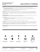


1. Shut o the power at the circuit breaker and remove existing xture, including the crossbar.
2. Carefully unpack your new xture and lay out all the parts on a clear area. Be careful not to lose any small parts necessary for installation.
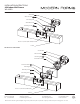
3. Remove the mounting screw (B) from the xture.
4. Connect the driver’s input wires to switch box wires as shown in , making sure that all wire connectors (A) are secured. If your outlet
box has a green or bare copper ground wire, connect the xture’s ground wire to it. Otherwise, connect the xture’s ground wire directly to
the mounting plate using the green screw provided. After wires are connected,tuck them carefully inside the switch box.
5. Secure the mounting plate to the switch box using standard switch box screws that comes with the switch box.
(i)using any other non-original-manufacturer provided switch box screw may result in safty issue;
(ii) The side of the mounting plate marked “GND” must face out.
6. Secure the xture to the mounting back plate using the mounting screw (B) .
3. Remove the mounting screw (B) from the xture.
4. Connect the driver’s input wires to switch box wires as shown in , making sure that all wire connectors (A) are secured. If your outlet
box has a green or bare copper ground wire, connect the xture’s ground wire to it. Otherwise, connect the xture’s ground wire directly to
the mounting plate using the green screw provided. After wires are connected,tuck them carefully inside the junction box.
5. Secure the mounting ring(D) to the junction box using standard junction box screws that comes with the junction box. Secure the mounting
plate and conversion plate(E) to the mounting ring(D) with assembly screw(C).
(i)using any other non-original-manufacturer provided junction box screw may result in safty issue;
(ii) The side of the mounting plate marked “GND” must face out.
6. Secure the xture to the mounting back plate using the mounting screw (B)
7. This xture features electronic low voltage (ELV or TRAIC) or 0-10V dimming capabilities. See notes below for specic dimming wires
information.
8. To utilize ELV or TRAIC dimming: use wires black (hot), white (neutral) and bare copper ground wire (ground).
9. To utilize 0-10V dimming: use wire purple (dim+), gray (dim-), black (hot), white (neutral) and bare copper ground wire (ground).
Make sure to connect 0-10V prior to power-up the xture in order to allow the 0-10V dimming to function properly.
Ø4"
1 3/4"
GND
1 3/8"
4 1/2"
1 5/8"
8"
1 3/8"
5 7/8"
2 1/2"
1 3/8"
1 5/8"
Black or
Smooth
White or
Ribbed
Bare wire
(Ground)
Black
(Hot)
White
(Neutral)
Green or Bare Copper
(Ground)
White - Neutral
Black - Hot
Purple - Dim+
Grdy - Dim-
Red - Fixtrue+
Black - Fixtrue-
3
INSTALLATION INSTRUCTIONS
WS-65023
Phone (800) 526.2588
Fax (800) 526.2585
44 Harbor Park Drive
Port Washington, NY 11050
1600 Distribution Ct
Lithia Springs, GA 30122
1750 Archibald Avenue
Ontario, CA 91760